Clamped piston perforating device capable of guaranteeing drilling stability based on reciprocating movement

A reciprocating motion and drilling device technology, which is applied in the direction of boring/drilling, drilling/drilling equipment, boring machine/drilling machine parts, etc., can solve the problems of huge vibration, poor stability, uneven drilling, etc. To achieve the effect of ensuring integrity, increasing linkage and high work efficiency

Inactive Publication Date: 2020-08-07
沈晶俊
View PDF9 Cites 2 Cited by
  • Summary
  • Abstract
  • Description
  • Claims
  • Application Information

AI Technical Summary

Problems solved by technology

[0003] The piston mainly includes several key steps such as material selection, rough forming, piston processing and quality inspection. On the drilling machine workbench, the current traditional punching machine has relatively simple functions, and it needs to be punched by a manual hand-held punching machine, and due to the huge vibration during the punching process, it is generally necessary to drill while punching in order to maintain stability. Hold it by hand. On the one hand, the vibration will cause the drilling to be uneven, which will cause inconvenience in later use. On the other hand, it will make the drilling staff more inconvenient and time-consuming when drilling
[0004] In order to solve the above problems, the inventor proposed a clampable piston drilling device based on reciprocating motion to ensure stable drilling. The problem of poor stability ensures that the operation of the device is more intelligent, and the automatic clamping ensures that it is more convenient to use, liberates the hands of workers, and saves time and effort

Method used


Image

  • Clamped piston perforating device capable of guaranteeing drilling stability based on reciprocating movement
  • Clamped piston perforating device capable of guaranteeing drilling stability based on reciprocating movement
  • Clamped piston perforating device capable of guaranteeing drilling stability based on reciprocating movement

Examples


Embodiment Construction

[0024] The following will clearly and completely describe the technical solutions in the embodiments of the present invention with reference to the accompanying drawings in the embodiments of the present invention. Obviously, the described embodiments are only some, not all, embodiments of the present invention. Based on the embodiments of the present invention, all other embodiments obtained by persons of ordinary skill in the art without making creative efforts belong to the protection scope of the present invention.

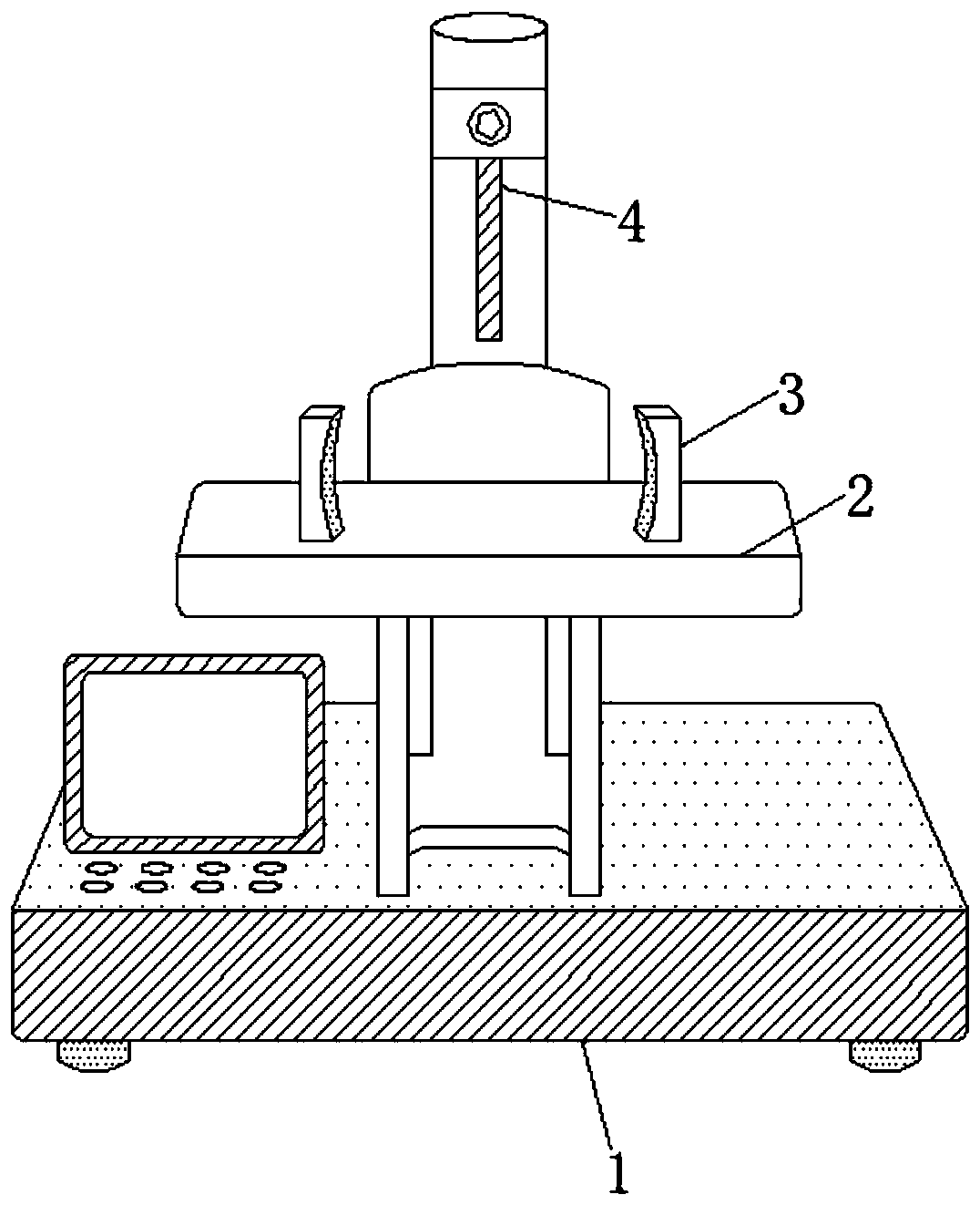
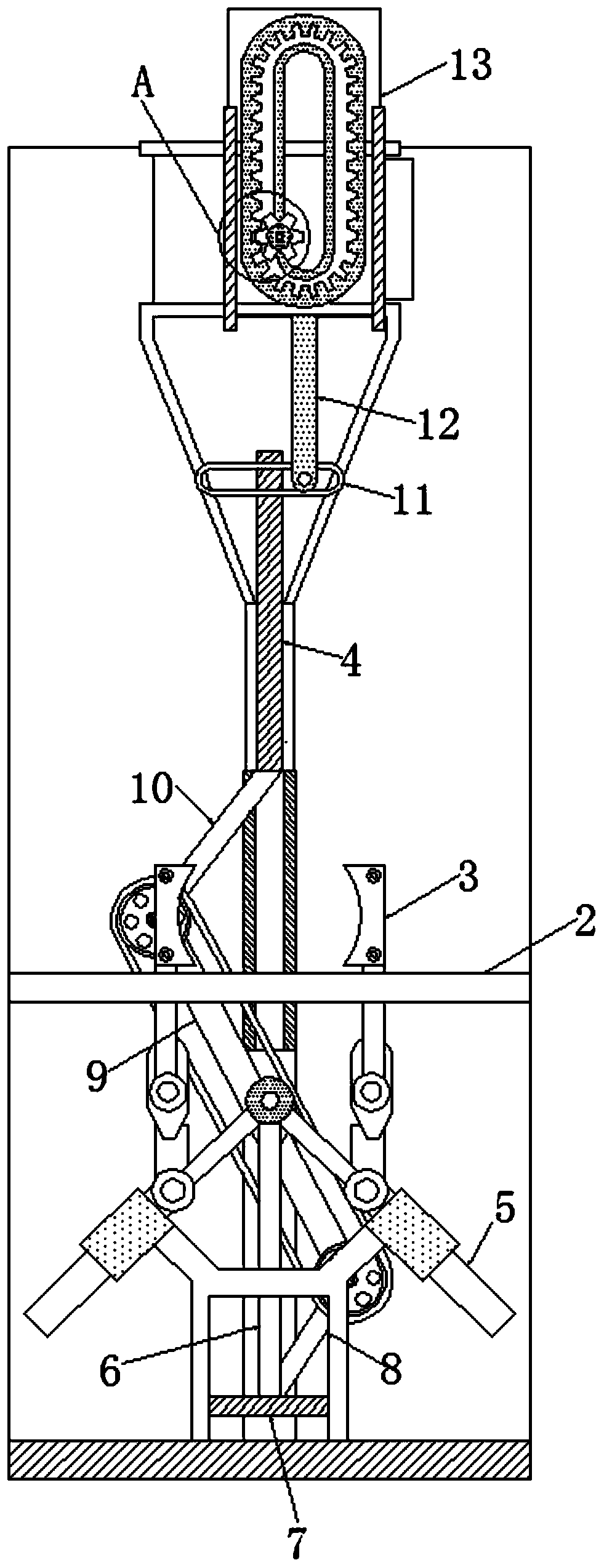
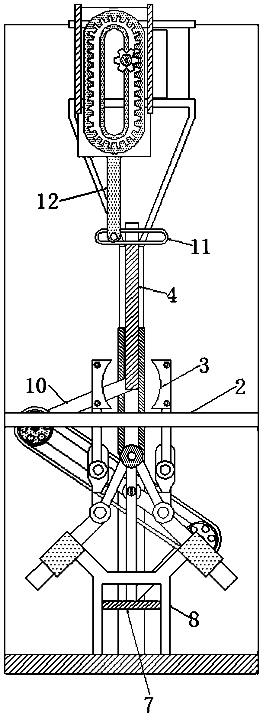
[0025] see Figure 1-5 , a clampable piston punching device based on reciprocating motion to ensure stable punching, including a base 1, a support plate 2 is fixedly connected above the base 1 to support raw materials, and a splint 3 is movably connected above the support plate 2 , the splint 3 is designed to be arc-shaped, and there are two splints 3, the specifications of the two splints 3 are consistent, and they are symmetrically distributed with the cente...


PUM


Abstract

The invention relates to the technical field of pistons, and discloses a clamped piston perforating device capable of guaranteeing drilling stability based on reciprocating movement. The clamped piston perforating device comprises a base, wherein a support plate is fixedly connected to the top of the base to support raw materials, clamping plates are movably connected to the top of the support plate, and are curved, so that clamping is stable; a driller is movably connected to the tops of the clamping plates; through cooperation of a limiting frame, a vertical rod, a movable plate and the driller for use, drilling is automatically completed, and an artificial operation is not needed, so that the drilling is convenient, and the working efficiency is high; through cooperation of the clampingplates, a connecting rod, a push rod and the movable plate for use, in the drilling process, clamping can be automatically completed, artificial supporting by hands is not needed, the drilling is stable, and the hole integrity is guaranteed; and through cooperation of a first support rod, a swinging rod and a second support rod for use, movement of a linkage structure can improve the linkage of the entire device, and the operation is simple.

Description

technical field [0001] The invention relates to the technical field of pistons, in particular to a grippable piston drilling device that ensures stable drilling based on reciprocating motion. Background technique [0002] The piston is a reciprocating part in the cylinder block of the automobile engine. With the increasingly strict requirements of the vehicle on the power, economy, environmental protection and reliability of the engine, the piston has developed into a new type of light weight and high strength. Materials, special-shaped outer circle compound surface, special-shaped pin hole and other high-tech products are very important for the processing and forging of pistons. [0003] The piston mainly includes several key steps such as material selection, rough forming, piston processing and quality inspection. On the drilling machine workbench, the current traditional punching machine has relatively simple functions, and it needs to be punched by a manual hand-held pu...

Claims


Application Information

Patent Timeline
Patent Type & Authority Applications(China)
IPC IPC(8): B23B41/00B23B47/00
CPCB23B41/00B23B47/00
Inventor 沈晶俊
Owner 沈晶俊
Why Eureka
Try Eureka