Device and method capable of achieving automatic reversing of vehicle in parking system
A parking system and automatic reversing technology, which is applied in the direction of buildings, building types, and buildings where cars are parked. It can solve the problems of inconvenient installation and maintenance, poor performance, and high production costs, and achieve easy transportation, good experience, and automation. high degree of effect
- Summary
- Abstract
- Description
- Claims
- Application Information
AI Technical Summary
Problems solved by technology
Method used
Image
Examples
Embodiment 1
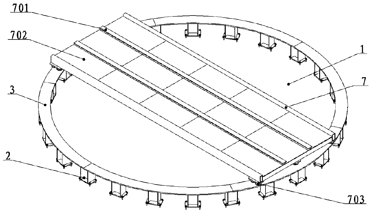
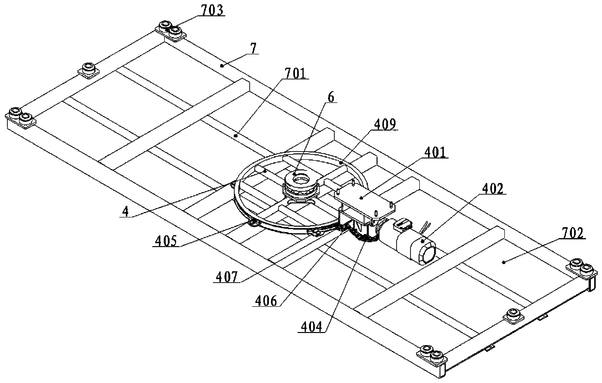
[0038] A mechanical device that can realize the automatic steering and U-turn of the vehicle in the parking system. Its assembly structure is as follows figure 1 with figure 2 As shown, it includes a bearing platform 1, a rotating track support 2, a rotating track 3, a transmission system 4, a second bearing seat 5, a second bearing 6, a rotating platform 7 and other connecting fasteners. Such as figure 1 As shown, the rotating track supports 2 are evenly distributed in the load-bearing platform 1, and the degree of density depends on the actual situation; the rotating track 3 is arranged on the rotating track support 2, which can be bent from profiles or multiple arcs It is formed by connecting circular plates, or it can be an integral ring; the rotating platform 7 includes a carrier walking track 701, a wheel pedal 702, and a universal ball 703. The carrier walking track 701 is set on the plane of the rotating platform 7, mainly as On the walking track of the vehicle carrier,...
Embodiment 2
[0041] The transmission system 4 can also be used without a steering wheel 406, such as Image 6 As shown, the traction chain 404 can be directly fixed to Picture 9 As shown in the groove of the rotary disc 409 (the groove is set to open outward), the drive sprocket 403 and the traction chain 404 adopt an external meshing method, and the drive sprocket 403 is driven to realize the rotation of the rotating platform 7 Spin.
Embodiment 3
[0043] According to the case of the transmission system 4 described in the second embodiment without the steering wheel 406, the Picture 9 The groove of the rotary disc 409 shown is set to open inward, that is, the inner groove structure, and the traction chain 404 is fixed in the inner groove of the rotary disc 409, such as Figure 7 As shown, the transmission sprocket 403 and the traction chain 404 are internally meshed, and the rotation of the rotating platform 7 is realized through the driving of the transmission sprocket 403.
PUM
 Abstract
Description
Claims
Application Information
 - R&D
- Intellectual Property
- Life Sciences
- Materials
- Tech Scout
- Unparalleled Data Quality
- Higher Quality Content
- 60% Fewer Hallucinations
Browse by: Latest US Patents, China's latest patents, Technical Efficacy Thesaurus, Application Domain, Technology Topic, Popular Technical Reports.
© 2025 PatSnap. All rights reserved.Legal|Privacy policy|Modern Slavery Act Transparency Statement|Sitemap|About US| Contact US: help@patsnap.com


