A magnetic energy accumulator

A technology of accumulators and magnetic energy, applied in the direction of actuator accumulators, mechanical equipment, fluid pressure actuation devices, etc., can solve problems such as potential safety hazards, energy storage loss, and explosive gas, achieving high safety and avoiding Explosion, the effect of ensuring stability

Active Publication Date: 2022-02-18
HUNAN UNIV OF TECH
View PDF0 Cites 0 Cited by
  • Summary
  • Abstract
  • Description
  • Claims
  • Application Information

AI Technical Summary

Problems solved by technology

There are many safety hazards and low energy storage accuracy in the way of gas compression to achieve energy storage, and it is prone to explosion or gas leakage, which leads to the loss of energy storage.

Method used


Image

  • A magnetic energy accumulator
  • A magnetic energy accumulator
  • A magnetic energy accumulator

Examples


Embodiment 1

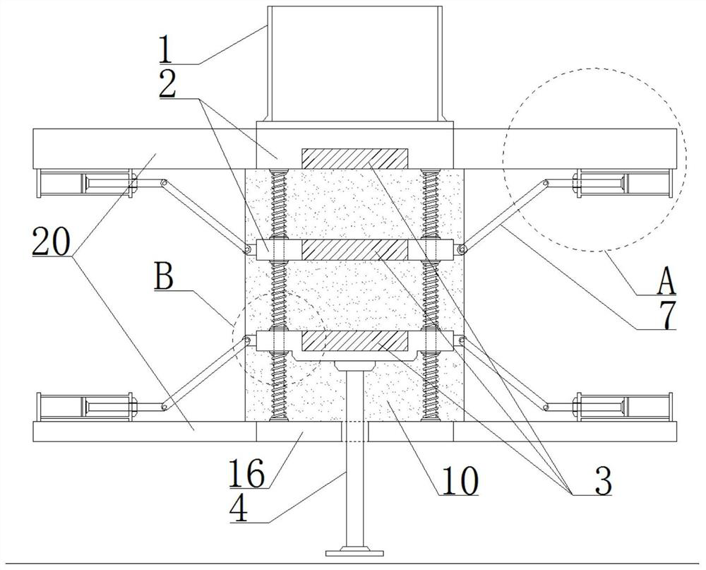
[0031] see Figure 1-9 , a magnetic energy accumulator, comprising a plurality of sets of magnetic mechanisms arranged up and down in sequence, a positioning mechanism, and an oil storage tank 1,

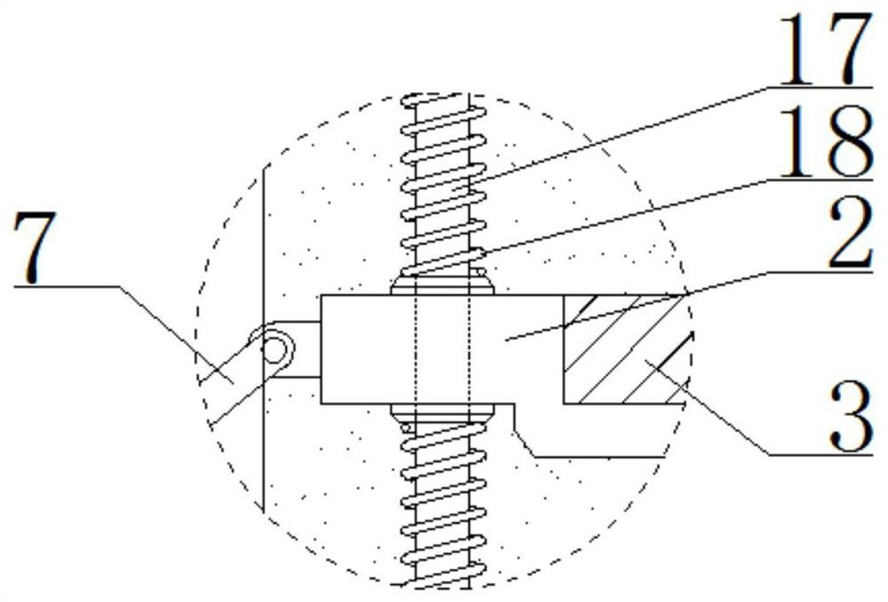
[0032] The magnetic mechanisms all include a mounting plate 2 and an electromagnet 3 nested in the mounting plate 2. Each group of magnetic mechanisms maintains relative movement along the vertical direction. The plates 2 remain relatively fixed, and each group of mounting plates 2 arranged below the uppermost layer is dynamically connected with a positioning mechanism, and the lower surface of the mounting plate 2 arranged at the lowest layer is consolidated with a power rod 4 and the power rod 4 is used as the energy of the accumulator. output input terminal;

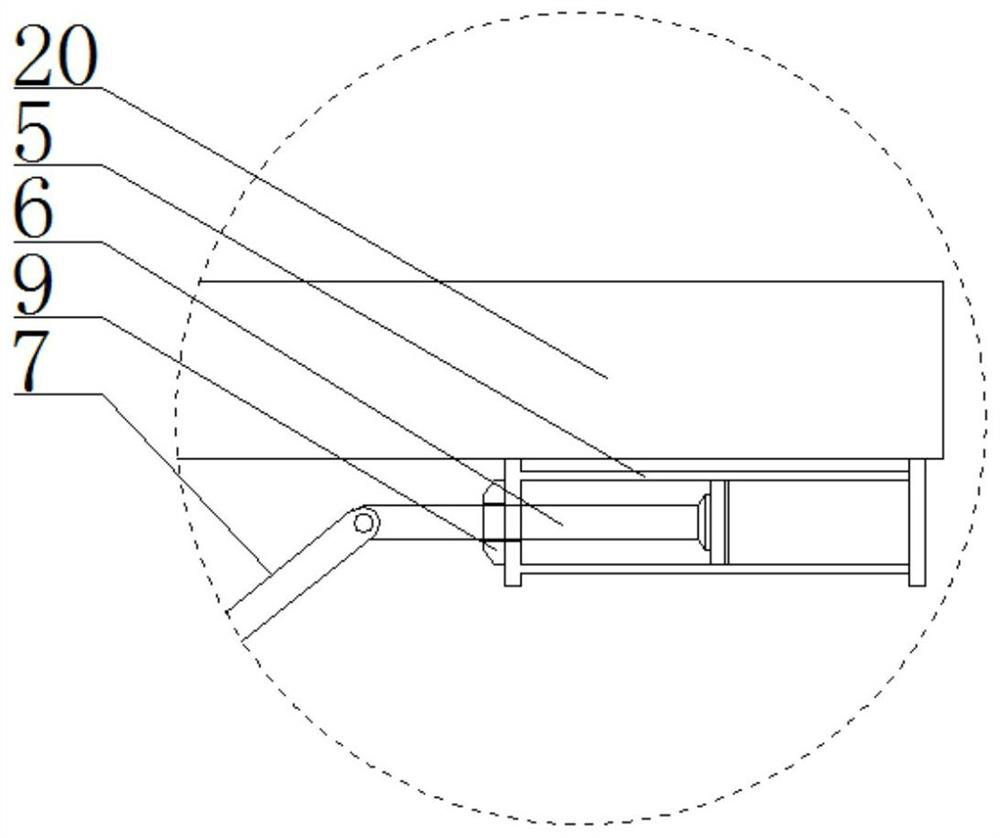
[0033] The positioning mechanism includes a positioning cylinder 5 and a positioning piston 6. The positioning piston 6 is nested in the positioning cylinder 5 and performs piston movement. The end of the positioning pisto...

Embodiment 2

[0035] see Figure 1-9 , to further describe Embodiment 1 in detail. In the present invention, the oil storage tank 1 is fixedly installed on the upper surface of the uppermost mounting plate 2, and under the action of no pressure, it can ensure that the hydraulic oil stored in the oil storage tank 1 flows in through the oil delivery pipe. Each group is positioned in the oil cylinder 5;

[0036] The mounting plate 2 and the corresponding electromagnet 3 are all in a cylindrical structure and arranged concentrically. A protective shell 10 is arranged on the periphery of each set of mounting plate 2. The overall structure of the protective shell 10 is a cylindrical structure to ensure that each group of magnetic mechanisms interacts stably and avoids The external environment and equipment affect it, and the protective shell 10 is provided with vertically arranged through holes relative to the direction in which the power rod 4 is set, so as to ensure that the movement of the mou...

Embodiment 3

[0039] see Figure 1-9 , the control principle of each electronic component and parts in the present application is explained: correspondingly connected with voltmeter 12, ammeter 13, circuit electronic switch 14 on the energization of each group electromagnet 3, voltmeter 12 is used for measuring electromagnet 3 when energizing Voltage value, ammeter 13 is used for the current value when electromagnet 3 is energized, circuit electronic switch 14 is used to control the on-off of the energized circuit of electromagnet 3, voltmeter 12, ammeter 13, circuit electronic switch 14, oil circuit electronic switch 8 The signal data of locking mechanism 9 is connected with single-chip microcomputer 15, through the single-chip microcomputer 15, the oil pipe is controlled to convey the on-off state of hydraulic oil to the corresponding positioning oil cylinder 5, and the on-off state of the energized circuit of the control electromagnet 3 is then controlled. Magnetic state, and the current...


PUM


Abstract

The invention discloses a magnetic energy accumulator. The magnetic mechanisms all include a mounting plate and an electromagnet nested in the mounting plate. Each group of magnetic mechanisms maintains relative movement along the vertical direction, and the magnetic poles of two adjacent groups of electromagnets face With the same setting, each group of mounting plates below the top layer is dynamically connected with a positioning mechanism, and the lower surface of the mounting plate on the bottom layer is consolidated with a power rod and used as the energy output and input end of the accumulator; the positioning mechanism includes a positioning cylinder, a positioning piston, The positioning piston is nested in the positioning oil cylinder and performs piston movement. The end of the positioning piston is hinged to the corresponding mounting plate through the connecting rod. The positioning oil cylinder is connected with the oil storage tank through the oil delivery pipe. The end of the positioning oil cylinder is provided with a locking mechanism that controls the movement state of the positioning piston. The invention has the beneficial effects of being able to be combined freely to meet energy storage requirements of different magnitudes, having stable energy storage and high safety.

Description

technical field [0001] The invention relates to the technical field of energy storage equipment, in particular to a magnetic energy accumulator. Background technique [0002] In the hydraulic system, since the piston action of each group of hydraulic cylinders and the elongation and shortening of the piston rod need to be controlled by hydraulic oil, because the hydraulic oil does not have compressibility, it is often impossible to store the hydraulic oil and store energy through it. The compression of the hydraulic oil realizes energy storage. At this time, it is necessary to use an accumulator for energy storage and connect the hydraulic oil pipe with the accumulator to gradually realize the energy storage of the hydraulic oil. [0003] But traditional accumulators often compress gas to store energy and release it when needed. There are many safety hazards and low accuracy of energy storage in the way of compressing gas to realize energy storage, and it is easy to cause e...

Claims


Application Information

Patent Timeline
Patent Type & Authority Patents(China)
IPC IPC(8): F15B1/04
CPCF15B1/04F15B2201/20F15B2201/40Y02E60/16
Inventor 熊勇刚杨小娟熊眭杨张勇米承继刘水长
Owner HUNAN UNIV OF TECH
Why Eureka
Try Eureka