An indoor range hood and its operation control method

A technology of range hood and fume collecting hood, which is applied in the fields of oil fume removal, heating method, household stove/stove, etc., can solve problems such as affecting user experience and reputation, poor smoke exhaust, affecting experience, etc., to improve combustion sufficiency and thermal efficiency, reducing extreme vacuuming, and improving the user experience

Active Publication Date: 2022-08-02
NINGBO FOTILE KITCHEN WARE CO LTD
View PDF11 Cites 0 Cited by
  • Summary
  • Abstract
  • Description
  • Claims
  • Application Information

AI Technical Summary

Problems solved by technology

However, the cooking habits of the Chinese people with cooking fume and the current situation of large air volume and high air pressure pursued by the existing range hoods make the air volume and pressure in the public flue large, so the problem of poor smoke exhaust often occurs
In addition, many users have the habit of closing the kitchen doors and windows when using range hoods. When the doors and windows are closed, vacuuming is likely to occur in the kitchen, resulting in increased inlet resistance. The indoor range hood flow rate cannot reach the target flow rate. Doors and windows are also difficult to open; on the other hand, many users feel that the kitchen is hot in summer, and kitchen air conditioners and coolers generally blow air from the top and circulate internally, which easily interferes with the flow field, resulting in poor oil suction effect and cold on the back of the head. , It is also easy to make the kitchen air conditioner and the fan blade of the cooling fan themselves polluted by the circulating oil fume air. After a period of use, it is difficult to clean up and there are peculiar smells, which affect the experience, and then affect the user experience and word of mouth.

Method used


Image

  • An indoor range hood and its operation control method
  • An indoor range hood and its operation control method
  • An indoor range hood and its operation control method

Examples


Embodiment Construction

[0033] The present invention will be described in detail below with reference to the embodiments of the accompanying drawings.

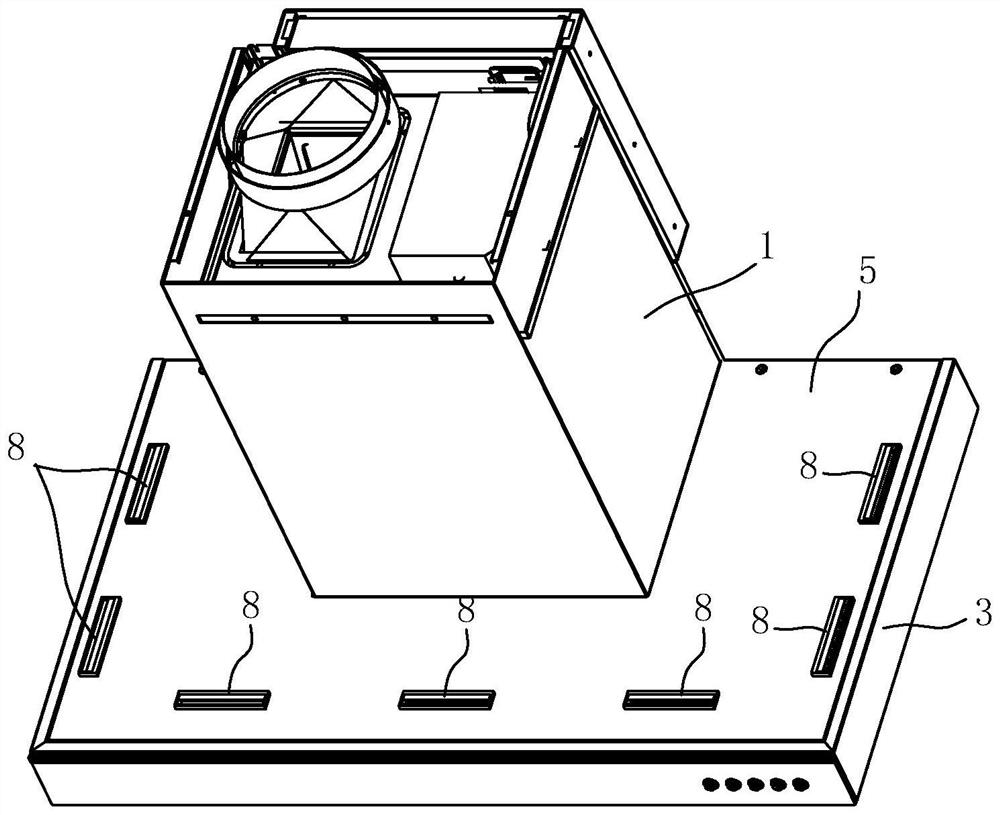
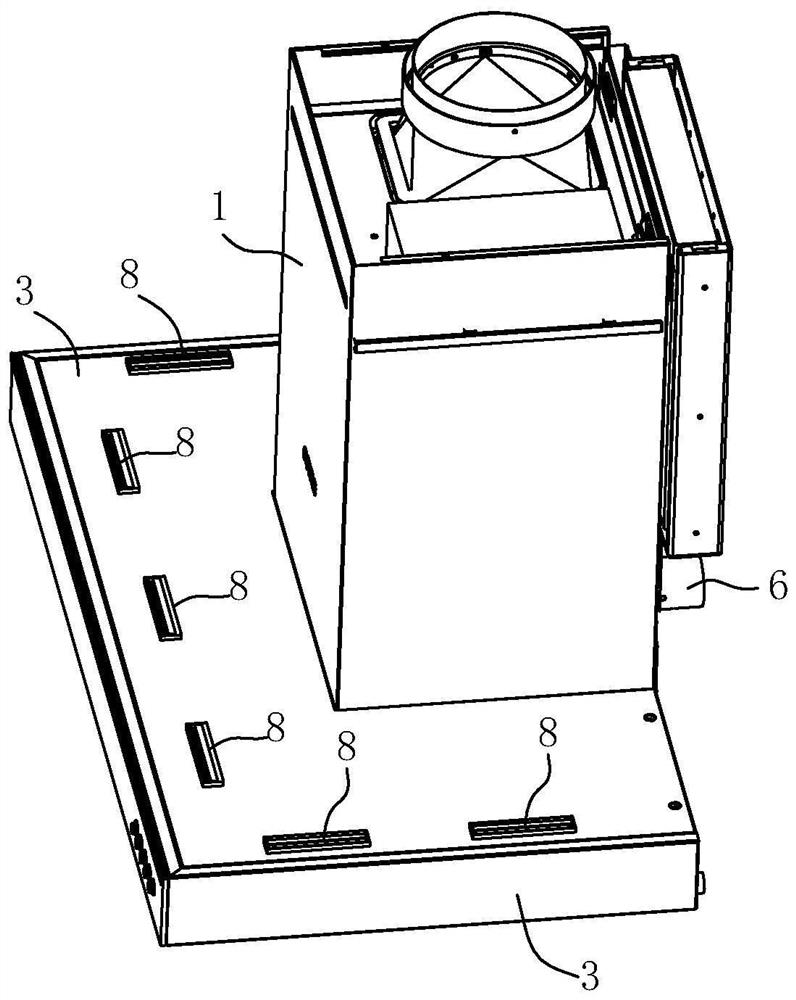
[0034] like figure 1 , 2 An indoor range hood shown in , 4 includes an upper casing 1, a fan system 2 is arranged in the upper casing 1, a fume collecting hood 3 is arranged under the upper casing 1, and an air inlet is arranged on the fume collecting hood 3 , the upper casing 1 is provided with an oil fume channel 4 that communicates with the air inlet of the fume collecting hood, the fan system 3 is located in the oil fume channel 4, and a top plate 5 is arranged above the fume collecting hood 3, and the top plate 5 is connected to the upper casing 1 Below, and a ring-shaped gap A is formed between the top plate 5 and the smoke collecting hood 3, the rear side of the upper casing is provided with a rear plate, and the rear plate is connected and fixed with a supplementary air pipe 6, and the supplementary air pipe 6 is provided with a supplementar...


PUM


Abstract

The invention relates to an indoor range hood and an operation control method thereof. The indoor range hood comprises an upper casing, a fan system, a fume collecting hood, a top plate is arranged above the fume collecting hood, the top plate is connected under the upper casing, and the top plate is connected with the upper casing. A gap is formed between the fume collecting hoods, which is characterized in that it also includes a supplementary air pipe, and a supplementary air valve is arranged in the supplementary air pipe. The gaps between the fume hoods communicate with each other, and air outlet components communicated with the gaps are arranged on the side surface or / and the top plate of the fume collecting hood. Compared with the prior art, the present invention has the advantages that fresh air can be actively introduced from the outside space of the kitchen, and the fresh air can easily form an outer surrounding flow field with the hot air near the cooker, thereby reducing the impact on the range hood when the doors and windows are opened and closed and other people move around. The interference of the nearby flow field can also provide the user with a facial blowing effect and improve the use experience.

Description

technical field [0001] The invention relates to an indoor range hood and an operation control method thereof. Background technique [0002] At present, most of the high-rise residential buildings adopt the centralized smoke exhaust method. The indoor range hood is connected to the public flue through a smoke pipe and a check valve, so that the oil fume in the kitchen is discharged into the public flue through the indoor range hood through the smoke pipe. However, the cooking habits of the Chinese people and the current large air volume and high air pressure pursued by the existing range hoods make the air volume and pressure in the public flue large, so the problem of poor smoke extraction often occurs. In addition, many users have the habit of closing the doors and windows of the kitchen when using the range hood. When the doors and windows are closed, vacuuming is easy to occur in the kitchen, resulting in an increase in the inlet resistance, and the flow rate of the indoo...

Claims


Application Information

Patent Timeline
Patent Type & Authority Patents(China)
IPC IPC(8): F24C15/20
CPCF24C15/20F24C15/2021
Inventor 何立博
Owner NINGBO FOTILE KITCHEN WARE CO LTD
Why Eureka
Try Eureka