Battery cycle tester and testing method thereof

A technology of battery cycle and test method, which is applied in the direction of instruments, measuring electronics, measuring devices, etc., can solve the problems of increased test cost, large energy consumption, and increased cost, and achieve the effects of reducing test cost, improving conversion efficiency, and saving costs

Active Publication Date: 2020-08-11
银河城泰山东科技有限公司
View PDF7 Cites 0 Cited by
  • Summary
  • Abstract
  • Description
  • Claims
  • Application Information

AI Technical Summary

Problems solved by technology

Energy needs to be obtained during the battery charging test, and the energy is generally connected to the load or fed back to the grid during the battery discharge test, which consumes a lot of energy and increases the test cost; when measuring battery packs with different numbers of strings, the required voltage and current requirements are different. Frequent replacement of test devices is inconvenient and increases costs, and if battery safety protection is not done well during battery testing, unnecessary losses will also be caused by testing

Method used


Image

  • Battery cycle tester and testing method thereof
  • Battery cycle tester and testing method thereof
  • Battery cycle tester and testing method thereof

Examples


Embodiment Construction

[0039] The specific implementation manners of the present invention will be further described in detail below in conjunction with the accompanying drawings and embodiments. The following examples are used to illustrate the present invention, but are not intended to limit the scope of the present invention.

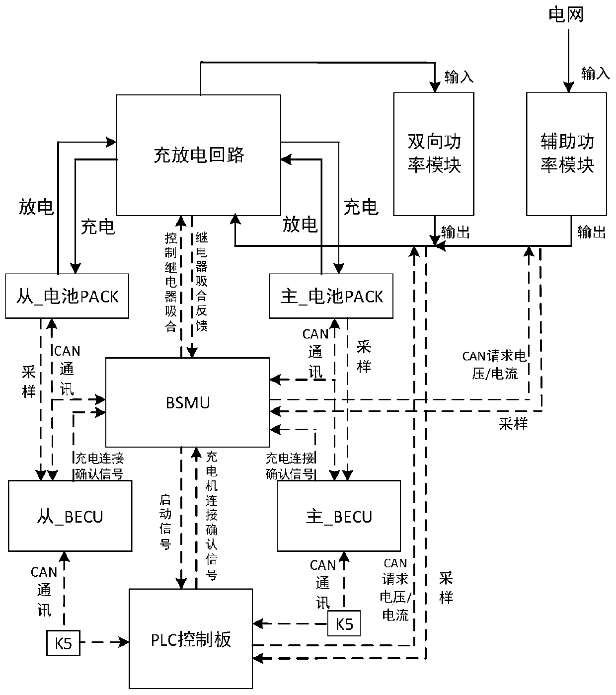
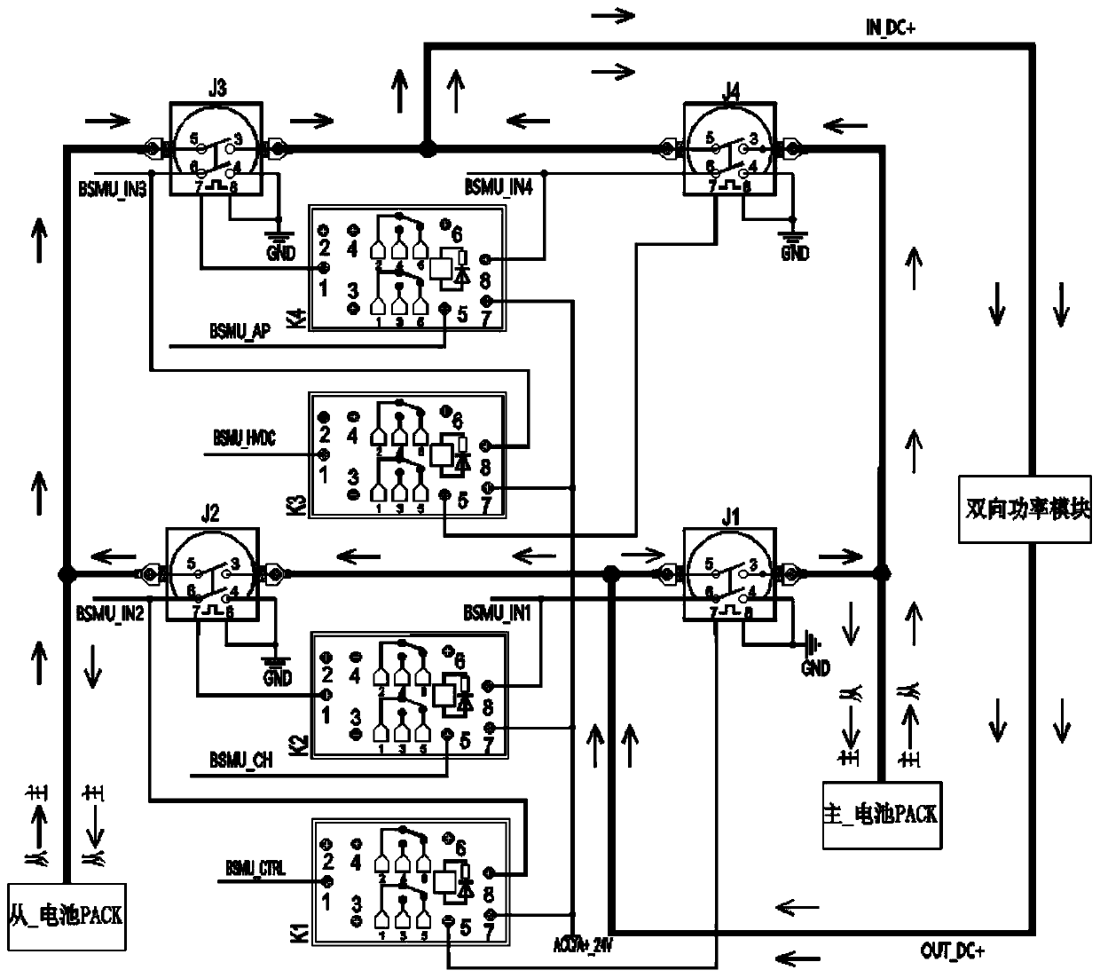
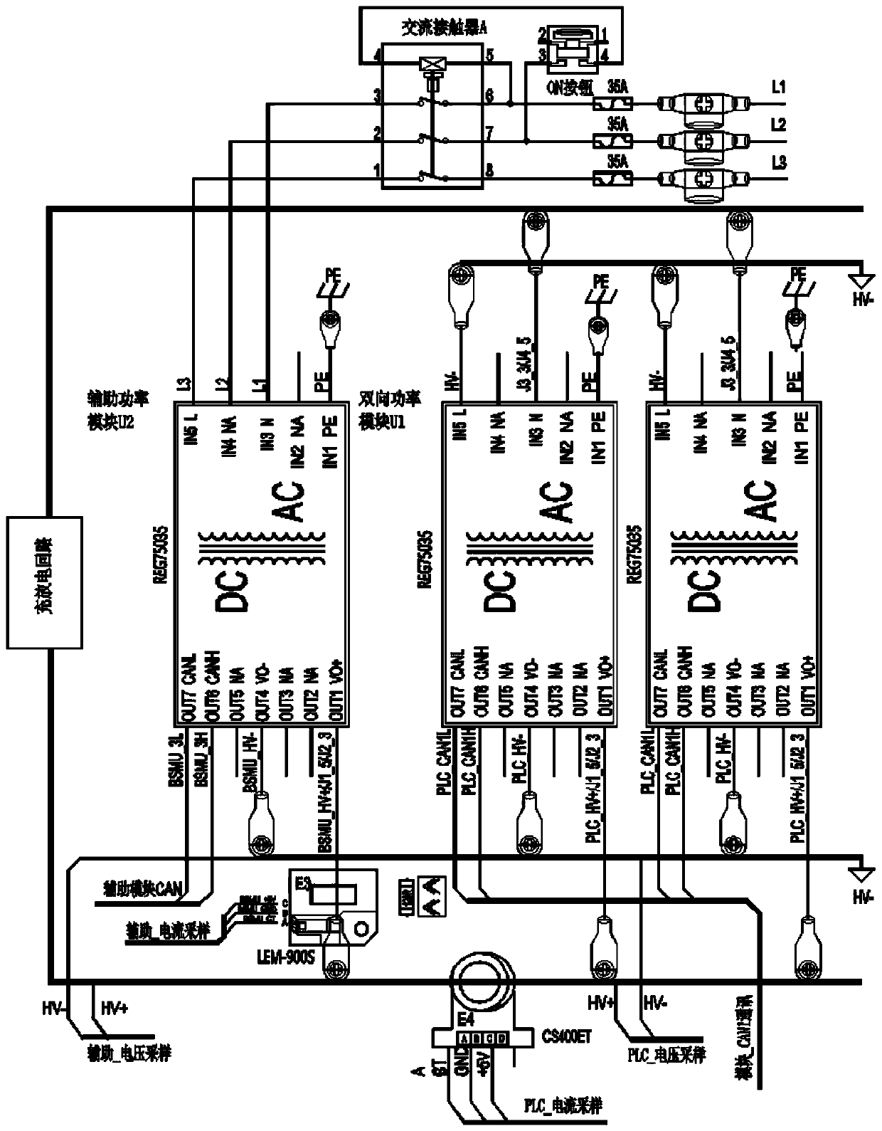
[0040] A battery cycle tester such as figure 1 As shown, including master_battery PACK, slave_battery PACK, charging and discharging circuit, bidirectional power module U1, auxiliary power module U2, master_BECU is BECU1, slave_BECU is BECU2, BSMU, PLC control board, for switching charging Direction relay K5, master_battery PACK_screen, slave_battery PACK_screen, charger screen and battery cycle test screen, the slave_battery PACK is the tested battery PACK, and the master_battery PACK is 8 sequentially The battery PACK groups PACK11-PCK18 connected in series, the slave_battery PACK is 8 sequentially connected battery PACK groups PACK21-PCK28, the bidirectional power modu...


PUM


Abstract

The invention discloses a battery cycle tester, which comprises a master _ battery PACK, a slave _ battery PACK, a charging and discharging circuit and a bidirectional power module, wherein the slave_ battery PACK is a tested battery PACK; the charging and discharging circuit comprises relays J1, J2, J3 and J4 and relays K1, K2, K3 and K4; the positive electrode of the slave _ battery PACK is connected with the common end I of the J3 and the common end I of the J2 through a high-voltage switch; the positive electrode of the main _ battery PACK is connected with a normally open contact I of the J4 and a normally open contact I of the J1, a normally open contact I of the J3 and a common end I of the J4 are connected with the positive electrode of the input end of the bidirectional power module, and a normally open contact I of the J2 and a common end I of the J1 are connected with the positive electrode of the output end of the bidirectional power module. The invention further disclosesa testing method of the battery cycle tester, and the discharge capacity of the tested battery PACK group can be recycled.

Description

technical field [0001] The invention relates to the field of battery technology, in particular to a battery cycle tester and a test method thereof. Background technique [0002] With the vigorous development of the new energy vehicle industry and the wide application of lithium-ion batteries, the role of lithium-ion battery packs is becoming more and more important. In order to ensure the consistency of the individual capacity of each battery pack, the battery pack cycle test refers to multiple charging and discharging of battery cells and lithium battery packs to perform life and reliability tests. Before the battery pack is delivered to the end customer, in order to ensure that each battery cell and battery pack can work normally, each lithium battery pack must be functionally tested after manufacturing. Energy needs to be obtained during the battery charging test, and the energy is generally connected to the load or fed back to the grid during the battery discharge test,...

Claims


Application Information

Patent Timeline
IPC IPC(8): G01R31/385G01R1/36
CPCG01R1/36G01R31/385
Inventor 吴浩王智张冬娟
Owner 银河城泰山东科技有限公司
Why Eureka
Try Eureka