Glue overflow detection device and glue overflow detection method

A detection device and glue overflow technology, which is applied in optical device exploration and other directions, can solve the problems of low detection accuracy, low detection efficiency, and affecting the detection accuracy of infrared proximity sensing holes, etc., and achieve the effect of simple detection method and high detection accuracy

Pending Publication Date: 2020-08-11
OPPO CHONGQING INTELLIGENT TECH CO LTD
View PDF8 Cites 3 Cited by
  • Summary
  • Abstract
  • Description
  • Claims
  • Application Information

AI Technical Summary

Problems solved by technology

[0004] However, the artificial visual inspection method is not only low in detection efficiency, but also low in detection accuracy. It can only be detected for completely overflowing glue or completely blocked holes (that is, the entire infrared proximity sensing hole is basically blocked), and for only slightly overflowed Infrared proximity sensing holes that are slightly blocked by plastic or slightly blocked, cannot be effectively inspected by manual visual inspection, which will affect the detection accuracy of the infrared proximity sensing holes

Method used


Image

  • Glue overflow detection device and glue overflow detection method
  • Glue overflow detection device and glue overflow detection method
  • Glue overflow detection device and glue overflow detection method

Examples


Embodiment 1

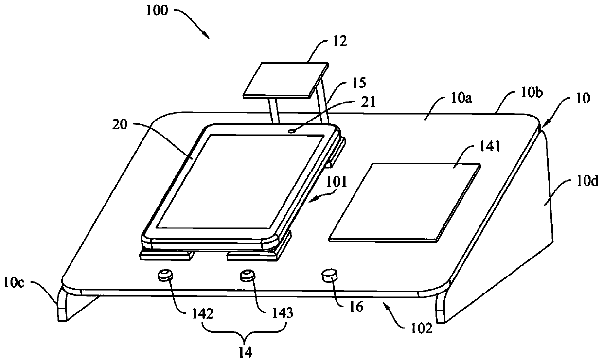
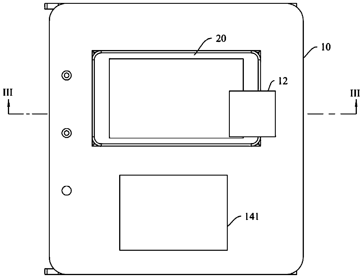
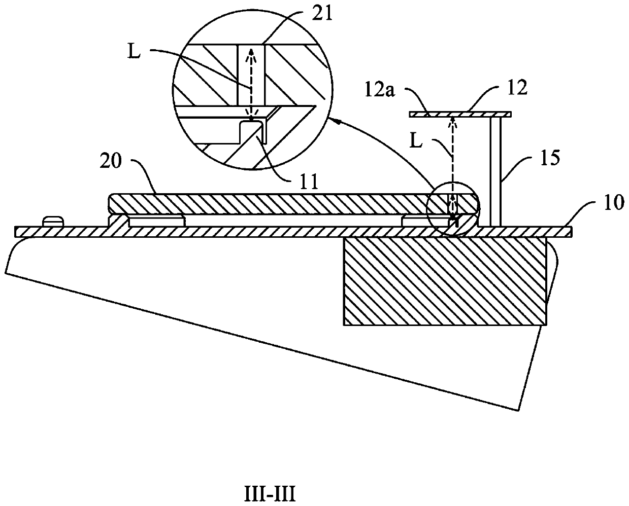
[0037] Please also refer to Figure 1 to Figure 4 , figure 1 shows a schematic structural view of the screen assembly of the electronic device placed in the glue overflow detection device of the present invention, figure 2 yes figure 1 side view, image 3 yes figure 2 Sectional view of III-III in, Figure 4 A schematic diagram of the screen assembly of the electronic device not placed in the glue overflow detection device is shown in . The glue overflow detection device 100 of this embodiment is used to detect the infrared proximity sensing hole 21 on the screen assembly 20 of the electronic device, so as to determine whether the infrared proximity sensing hole 21 has glue overflow or hole blocking phenomenon. The glue overflow detection device 100 of the present embodiment includes a detection table 10, an optoelectronic device 11, a baffle 12, and a controller 13 (see Figure 5 shown) and the output unit 14. Wherein, there is a positioning position 101 on the table ...

Embodiment 2

[0063] Please also refer to figure 1 and Figure 6 , Figure 6 It is a flowchart of the glue overflow detection method disclosed in Embodiment 2 of the present invention. The glue overflow detection method in this embodiment 2 is realized by using the glue overflow detection device 100 in the above-mentioned embodiment 1. The glue overflow detection method includes:

[0064] 201. Place the screen assembly of the electronic device on the table top of the inspection table, and make the infrared proximity sensing hole on the screen assembly correspond to the optoelectronic device.

[0065] In this embodiment, during detection, the screen assembly 20 needs to be placed on the positioning position 101 of the detection table 10, and the position of the screen assembly 20 should be kept so that the screen assembly 20 remains still during the detection process. Avoid the displacement of the screen component 20 from affecting the detection result.

[0066] As an optional implementa...


PUM


Abstract

The invention discloses a glue overflow detection device and a glue overflow detection method. The glue overflow detection device comprises a detection table, an optoelectronic device, a baffle, a controller and an output part. The detection table is used for positioning a screen assembly of the electronic device. The optoelectronic device is arranged on the detection table, and is configured to be arranged corresponding to an infrared proximity sensing hole in a screen assembly. The baffle plate is arranged on the detection table, and is provided with a reflecting surface facing the detectiontable. The controller is electrically connected with the optoelectronic device, the output component is electrically connected with the controller, the optoelectronic device is used for emitting first light waves to the infrared proximity sensing hole and collecting first luminous flux to be fed back to the controller, and the controller is used for comparing the first luminous flux with preset luminous flux and controlling the output component to output a detection result. By the adoption of the embodiment, whether glue overflow happens to the infrared proximity sensing hole or not can be effectively detected, the detection mode is simple and rapid, manual visual inspection is not needed, the glue overflow condition of the infrared proximity sensing hole with slight glue overflow can bedetermined more rapidly, and the detection precision is high.

Description

technical field [0001] The invention relates to the technical field of electronic equipment, in particular to a glue overflow detection device and a glue overflow detection method. Background technique [0002] In the related art, an infrared proximity sensing hole is usually provided on the upper cover of the electronic device, and the infrared proximity sensing hole is set corresponding to the infrared proximity sensor in the electronic device, so as to realize the infrared proximity sensing function of the electronic device. Usually, the upper cover of the electronic device needs to be assembled to the screen after dispensing to form a screen assembly of the electronic device. In the dispensing process of the upper cover of electronic equipment, affected by factors such as the accuracy of the dispensing equipment, the glue path, and the amount of glue, it is easy for some glue to overflow into the infrared proximity sensing hole after the glue is pressed open, resulting i...

Claims


Application Information

Patent Timeline
Patent Type & Authority Applications(China)
IPC IPC(8): G01V8/12
CPCG01V8/12
Inventor 宋子一
Owner OPPO CHONGQING INTELLIGENT TECH CO LTD
Why Eureka
Try Eureka