
Output waveguide window for Ka-waveband high-power space traveling-wave tube

An output waveguide, high-power technology, applied in the field of microwave electric vacuum devices, can solve the problems of poor heat dissipation, difficult to meet the reliability of Ka-band high-power space traveling wave tubes, etc., achieve good heat dissipation performance, meet heat dissipation problems and high frequency Loss problem, high reliability effect

Active Publication Date: 2020-08-11
AEROSPACE INFORMATION RES INST CAS
View PDF6 Cites 3 Cited by
  • Summary
  • Abstract
  • Description
  • Claims
  • Application Information

AI Technical Summary

Problems solved by technology

Moreover, the material used is Kovar with poor heat dissipation, which has been difficult to meet the reliability requirements of the Ka-band high-power space traveling wave tube.

Method used


Image

  • Output waveguide window for Ka-waveband high-power space traveling-wave tube
  • Output waveguide window for Ka-waveband high-power space traveling-wave tube

Examples


Embodiment Construction

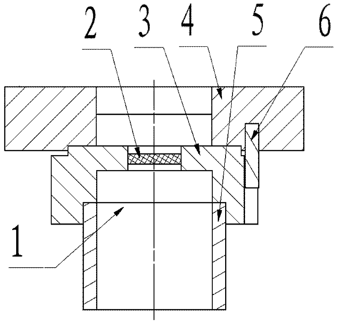
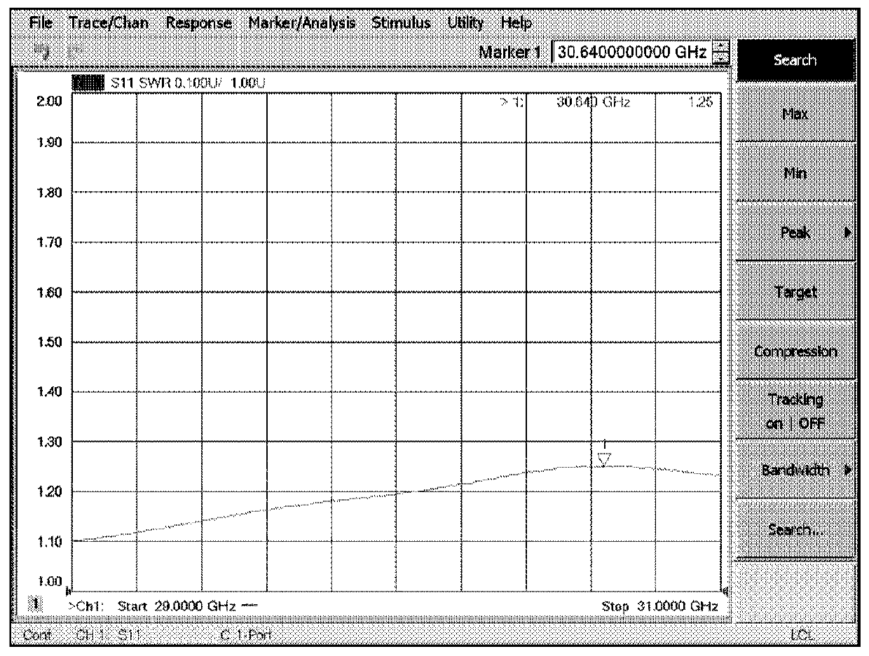
[0039] The present disclosure provides an output waveguide window for a Ka-band high-power space traveling wave tube, including: a window, a sealing member, a waveguide flange and a transitional waveguide, the sealing member is sleeved on the outside of the window, and the The sealing part is sealed and connected to the circumference of the window; the waveguide flange is connected to the upper side of the sealing part; the transitional waveguide is sleeved on the lower side of the sealing part and connected to the seal; A vacuum cavity is formed inside the waveguide. The structure is simple, the reliability is high, and the traveling wave tube meets the requirements of small standing wave, temperature shock resistance, mechanical vibration resistance, and good heat dissipation performance.

[0040] In order to make the purpose, technical solutions and advantages of the present disclosure clearer, the present disclosure will be further described in detail below in conjunction ...


PUM


Abstract

The invention provides an output waveguide window for a Ka-waveband high-power space traveling wave tube. The window comprises a window piece, a sealing piece, a waveguide flange and a transition waveguide, and is characterized in that the sealing piece sleeves the outer side of the window piece and is connected with the circumference of the window piece in a sealing manner; the waveguide flange is connected with the upper side of the sealing piece; the transition waveguide sleeves the lower side of the sealing piece and is hermetically connected with the sealing piece; and a vacuum cavity isformed in the sealing piece, the waveguide flange and the transition waveguide. The structure is simple, the reliability is high, and the requirements of small standing wave, temperature impact resistance, mechanical vibration resistance and good heat dissipation performance of the traveling wave tube are met.

Description

technical field [0001] The present disclosure relates to the field of microwave electric vacuum devices, in particular to an output waveguide window for a Ka-band high-power space traveling wave tube. Background technique [0002] The traveling wave tube is a microwave tube that realizes the amplification function by continuously modulating the speed of the electron beam. The microwave signal to be amplified enters the slow wave circuit through the input window and travels along the slow wave circuit. The electrons exchange energy with the traveling microwave field, so that the microwave signal is amplified, and then output through the output window. Therefore, the output window of the traveling wave tube directly affects the loss of the traveling wave tube, the quality of the characteristic impedance matching, and the narrow frequency bandwidth. [0003] With the improvement of band bandwidth, output power, reliability, and thermal design (including loss and heat dissipati...

Claims


Application Information

Patent Timeline
Patent Type & Authority Applications(China)
IPC IPC(8): H01J23/00H01J23/12H01J23/36
CPCH01J23/005H01J23/36H01J23/12
Inventor 刘泳良唐康淞缪国兴高察王建王庆祥李芬翟德慧
Owner AEROSPACE INFORMATION RES INST CAS
Learn More