Fuel delivery device for cryogenic fuels

A technology of fuel delivery and low-temperature fuel, which is applied to fuel injection devices, fuel supply devices, fuel injection pumps, etc.

Active Publication Date: 2020-08-11
ROBERT BOSCH GMBH
View PDF8 Cites 1 Cited by
  • Summary
  • Abstract
  • Description
  • Claims
  • Application Information

AI Technical Summary

Problems solved by technology

In particular, transverse forces lead to increased wear in the area of ​​the guide and / or seal on the pump piston, which in turn has a negative effect on the service life of the piston pump

Method used


Image

  • Fuel delivery device for cryogenic fuels
  • Fuel delivery device for cryogenic fuels
  • Fuel delivery device for cryogenic fuels

Examples


Embodiment Construction

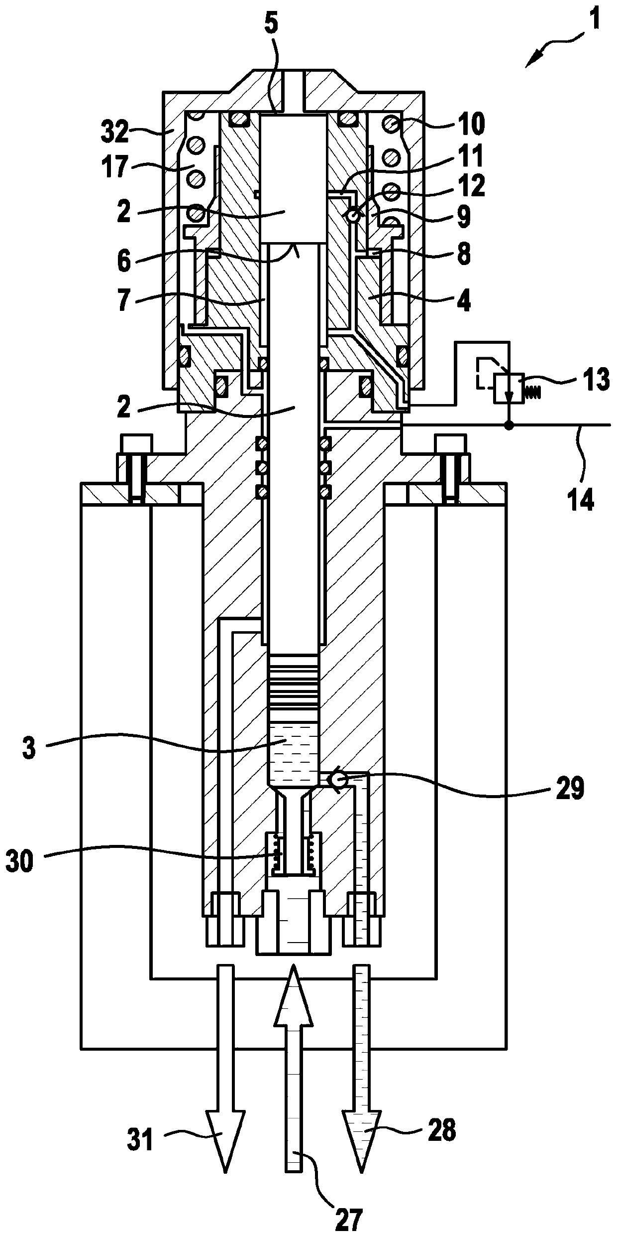
[0035] exist figure 1 The fuel delivery device according to the invention shown in is used to supply fuel to an internal combustion engine (not shown) of a motor vehicle, wherein the fuel is a cryogenic fuel, preferably natural gas. The fuel delivery device comprises a piston pump 1 for delivering fuel to high pressure.

[0036] Fuel is stored in liquid form in tanks (not shown). Via the inflow opening 27 and the suction valve 30 , the fuel reaches the compression chamber 3 of the piston pump 1 , which is delimited by the reciprocating pump piston 2 . During the working stroke of the pump piston 2 , the fuel present in the compression chamber 3 is compressed and supplied via the outflow opening 28 to a buffer accumulator (not shown). A non-return valve 29 is arranged in the region of the outflow opening 28 in order to prevent fuel from flowing back into the compression chamber 3 during a new suction stroke of the pump piston 2 . Furthermore, a return line 31 is provided for...


PUM


Abstract

The invention relates to a fuel delivery device for cryogenic fuels, comprising a piston pump (1) for delivering the cryogenic fuel at a high pressure, said piston pump (1) having a pump piston (2) that can be moved back and forth and delimits a compression chamber (3) at one end and a pressure chamber (5), which is formed in a hollow cylinder (4) and to which a hydraulic pressure medium can be supplied, at the other end. According to the invention, the pump piston (2) has an annular shoulder (6) for delimiting an additional pressure chamber (7) which is formed in the hollow cylinder (4) and to which the hydraulic pressure medium can likewise be supplied in order to reset the pump piston (2). The additional pressure chamber (7) is coupled to an accumulator volume (8) which is delimited byan accumulator sleeve (9) that is arranged on the hollow cylinder (4) in a movable manner back and forth and is biased by means of a return spring (10).

Description

technical field [0001] The invention relates to a fuel delivery device for cryogenic fuels having the features of the preamble of claim 1 . Background technique [0002] The cryogenic fuel may in particular be natural gas ("Natural Gas"=NG), which is stored in liquid form ("Liquefied Natural Gas"=LNG) in tanks specially designed for this purpose, for example in motor vehicles for operating internal combustion engines. [0003] From EP 2 541 062 A1 a piston pump for cryogenic fuels, in particular natural gas, is known which has a reciprocating pump piston. The pump piston delimits a pump working chamber which can be filled with liquefied natural gas, so that the liquefied natural gas present in the pump working chamber can be acted upon with high pressure by reciprocating the pump piston. At the other end, the pump piston delimits a coupling chamber which can be filled with hydraulic pressure medium in order to drive the pump piston in a reciprocating movement. Alternativel...

Claims


Application Information

Patent Timeline
IPC IPC(8): F04B9/105F04B15/08F02M21/02
CPCF04B9/105F04B9/1053F04B15/08F02M21/0245F04B2015/081F02M59/105
Inventor D·施尼特格F·豪伊
Owner ROBERT BOSCH GMBH
Why Eureka
Try Eureka