
Eureka
For R&D, Eureka makes reading and utilizing patents & technical documents easy.
Eureka AIR
Designed for self-driven R&D workflows. Generate viable solutions, solve complex R&D challenges, empower your innovation with AI.

Eureka Materials
Designed for material experts only. Revolutionize your material R&D, from search, analyze, to developing new materials.

TechResearch
Generate reliable direction feasibility study reports for your R&D in just a few steps.

TechSeek
Discover and master advanced knowledge NOW. Basics, ideas, possibilities, all at once.

TechMind
As an expert in R&D Theories, TechMind can generates customized viable solutions instantly.

TechRisk
Analyze your overall solution with one click, know your potential R&D risks in advance.

TechMonitor
Get weekly tech updates, stay abreast of the latest tech innovations and key insights.
A method and a jig for manufacturing a pin-fin type power module
A power module and fixture technology, which is applied in semiconductor/solid-state device manufacturing, semiconductor/solid-state device parts, semiconductor devices, etc., can solve the problem of uneven pressure on insulating materials, cracking of insulating materials and pin-fin substrates, uneven external forces, etc. question
- Summary
- Abstract
- Description
- Claims
- Application Information
AI Technical Summary
Problems solved by technology
Method used
Image

Examples
Embodiment 1
[0023] Example 1 :refer to Figure 4-Figure 8 , manufacture the pin-fin power module through the following steps:
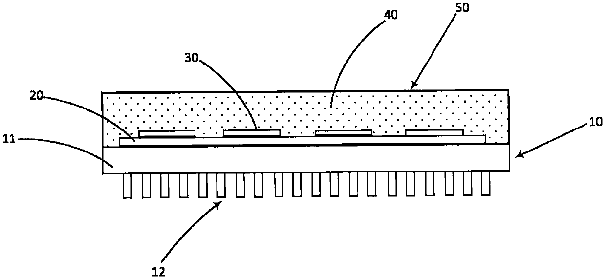
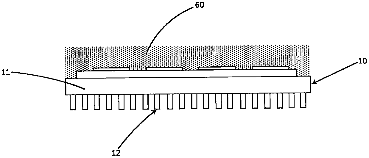
[0024] First, a pin-fin type power module and a clamp 9 are provided. The power module includes a pin-fin substrate 1 , an insulating material (DBC) 2 connecting the substrate 1 , and a power chip 3 disposed on the DBC 2 . The substrate 1 has a first surface 11 and a second surface 12 opposite to the first surface 11 . The first surface 11 is connected to the DBC 2 and the second surface 12 has several fins 121 on it. The jig 9 includes a carbon body with a flat upper surface and a flat lower surface, and several through holes 91 are provided on the upper surface of the body, wherein the distribution of the through holes is the same as that of the fins, and the diameter of the holes is larger than the size of the fins. , and the length of the through hole is the same as the length of the fin.
[0025] Insert the pin-fin into the jig as Figure 6 As shown i...
Embodiment 2
[0028] Example 2 : now refer to Figure 9 to Figure 10 , in an alternative solution a stainless steel clamp 9 with a blind hole 91 is used. The blind holes are the same length as the fins. Before molding, all the fins 121 are inserted into the corresponding blind holes 91 by arrow A, and then the pin-fins are stably supported by the jig. The jig with blind holes is sufficiently stable that the pressure on the power module is evenly distributed during the molding process.
Embodiment 3
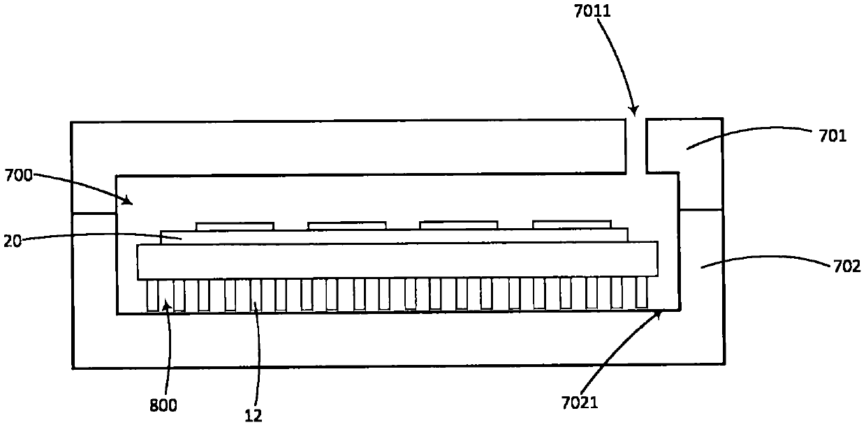
[0029] Example 3 : now refer to Figure 11 , in another alternative fixture, blind holes 91 are provided, but the length of the blind holes 91 is longer than the length of the fins 121, so there is a vertical gap 800 between each fin and the corresponding blind hole. The vertical direction is parallel to the length direction of the fins.
PUM
 Abstract
Description
Claims
Application Information
 - R&D Engineer
- R&D Manager
- IP Professional
- Industry Leading Data Capabilities
- Powerful AI technology
- Patent DNA Extraction
Browse by: Latest US Patents, China's latest patents, Technical Efficacy Thesaurus, Application Domain, Technology Topic, Popular Technical Reports.
© 2024 PatSnap. All rights reserved.Legal|Privacy policy|Modern Slavery Act Transparency Statement|Sitemap|About US| Contact US: help@patsnap.com