
Novel movable disinfection door suitable for various occasions

A new and occasional technology, applied in applications, medical science, sensors, etc., can solve the problems of gathering of passers-by, increasing the risk of infection, time-consuming and labor-intensive problems, and achieve the effect of ensuring the disinfection effect, reducing manual labor, and avoiding contact

Inactive Publication Date: 2020-08-14
南京默思泰智能科技有限公司
View PDF9 Cites 4 Cited by
  • Summary
  • Abstract
  • Description
  • Claims
  • Application Information

AI Technical Summary

Problems solved by technology

[0002] In response to the current outbreak of the new coronavirus, major communities, shopping malls, office buildings and all crowded places have to be closed. Even so, there are still people who need to enter and exit the area. When people have to enter and exit the area, the clothing of the personnel If the appearance is contaminated with bacteria and viruses, it is difficult for security personnel to grasp the situation;
[0003] Due to the characteristics of the virus, the current epidemic prevention and control work can only set up access control areas and conduct simple disinfection and temperature measurement of passers-by. The manual inspection method is not only time-consuming and laborious, but also greatly limits the efficiency of the flow of people, which is easy to cause the gathering of passers-by. The risk of infection in the area is increased, and there is no systematic disinfection and investigation method, making it difficult to ensure the safety of passing disinfection

Method used


Image

  • Novel movable disinfection door suitable for various occasions
  • Novel movable disinfection door suitable for various occasions
  • Novel movable disinfection door suitable for various occasions

Examples


Embodiment 1

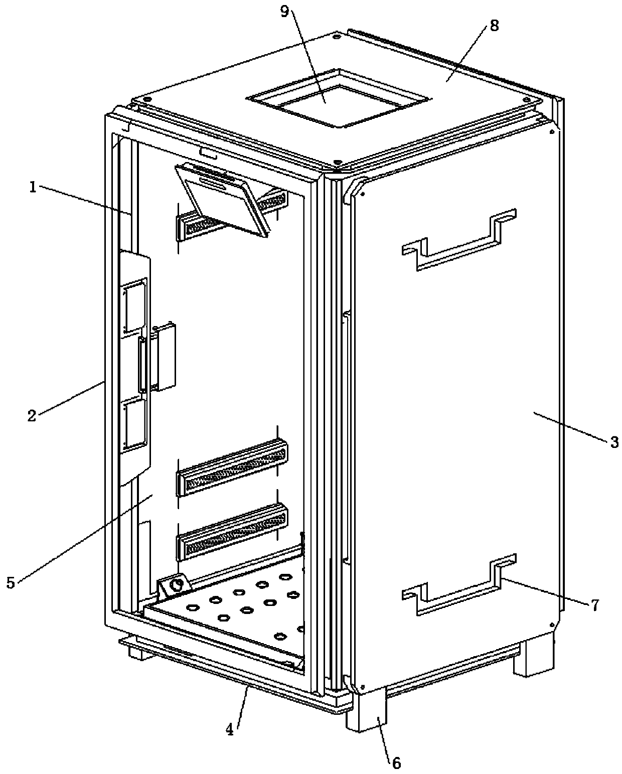
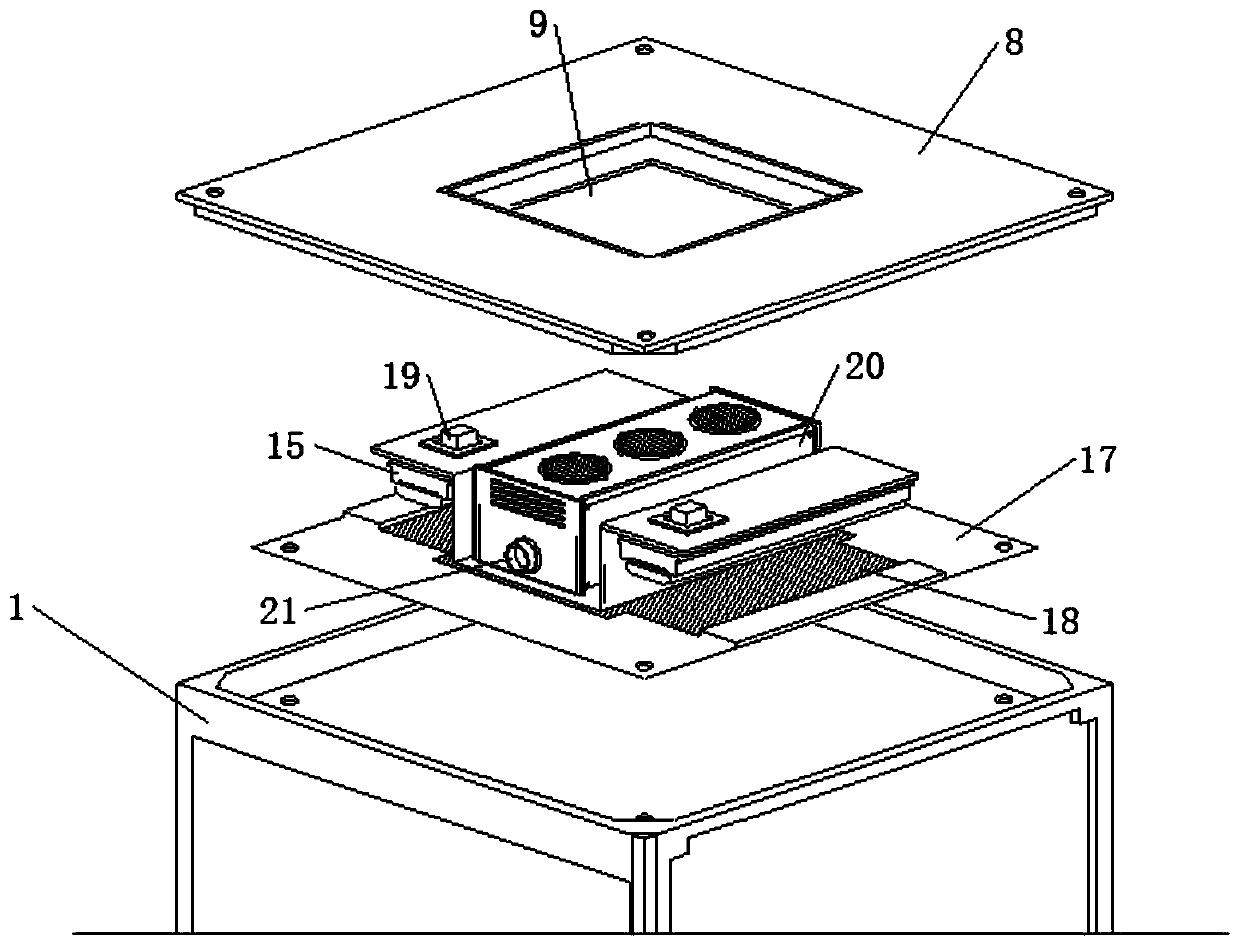
[0043] Passers-by enter and exit the door frame 2 through the front and before stepping into the disinfection room 5, the control panel 22 will drive the infrared panel 16 to run through the PLC system. The reflected radiant energy will increase the temperature of the sensor to identify and collect the temperature of the human face, and obtain the normal body temperature according to the corresponding formula of body temperature in each area of ​​the human body, which will be displayed by the display screen in the infrared panel 16 and then recorded by the control panel 22 system to complete the process of passing personnel. temperature measurement.

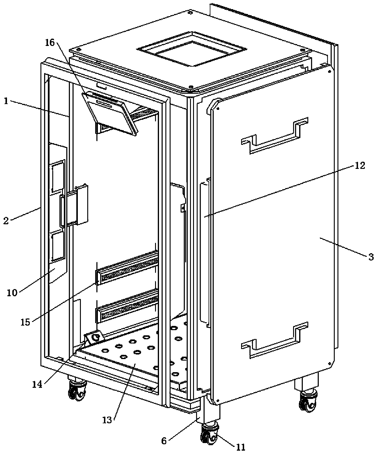
[0044] The middle part of detection board 10 is plugged with telescopic slide rail 29, and slide seat 30 is slidably connected between telescopic slide rail 29 and disinfection door frame 1, and slide seat 30 is fixedly connected with side wall of disinfection door frame 1, and the door frame 2 passes through telescopic slide rail...

Embodiment 2

[0046] On the basis of the above embodiments, when using the disinfection door, the staff needs to pull the entry and exit door frame 2 to the outside of the front and rear ends of the disinfection chamber 5, so that the telescopic slide rail 29 in the entry and exit door frame 2 slides along the slide seat 30, by figure 1 stretch to figure 2 As shown, when the passer-by enters / steps out of the disinfection chamber 5 through the door frame 2, the human body will block the infrared light 28 in the detection board 10 from shooting against the infrared light 28 based on the working principle of the infrared grating, thereby generating an instantaneous signal of the passing of the human body and sending it to The control panel 22 is used to provide the control panel 22 with information about the entry and exit of personnel, and to control the operating time of the equipment in the disinfection room 5 .

[0047] A pair of side movable plates 3 are symmetrically arranged on the lef...

Embodiment 3

[0050] To move and install the disinfection door, the staff can respectively hold the pull ring groove 7 on one side and lift it upwards. At this time, the level of the disinfection door frame 1 rises, the swing arm 24 is no longer under pressure, and the spring tube 27 acts elastically in the compressed state. Finally, the swing arm 24 will rotate along the movable bearing 26 until the swing arm 24 is laterally inserted into the shaft bushing 23 to fix it, and as the swing arm 24 is stretched, the universal wheel 11 fixed at the lower end of the swing arm 24 will be fixed at the lower end of the leg 6 After the staff releases the pull ring groove 7, they can move by pushing the disinfection door. After moving to the designated place, the staff will hold the pull ring groove 7 with a relatively weak lifting force, and maintain the level of the disinfection door. , the front end of the foot knocks the universal wheel 11 inward until the swing arm 24 is separated from the shaft s...


PUM


Abstract

The present invention discloses a novel movable disinfection door suitable for various occasions and belongs to the technical field of disinfection safety. The novel movable disinfection door comprises a disinfection door frame, an in-and-out door frame, a base seat and a top cover; a disinfection chamber running through a front end an rear end is formed in the disinfection door frame, three pairsof ultraviolet lamp tubes are symmetrically arranged on a left side and a right side of the disinfection chamber, the ultraviolet lamp tubes are embedded in the disinfection door frame, a pedal platform is arranged at a bottom end of the disinfection chamber, and two pairs of sterilizer nozzles are clamped on a left side and a right side of the pedal platform; the sterilizer nozzles are internally embedded with disinfectant boxes, lower left ends of the sterilizer nozzles are provided with disinfectant pipes in a penetrating manner and the disinfectant pipes communicate with the disinfectantboxes. The disinfection door conducts high-efficient and contactless disinfection of passing people through a cooperation manner of ultraviolet radiation sterilization and multiple spot spraying, andavoids contact infection of staff and passing people. Besides, the movable structure facilitates laying of the disinfection door and entrance guard passing region, and improves suitability and practicality of the disinfection door.

Description

technical field [0001] The invention relates to the technical field of disinfection safety, in particular to a novel mobile disinfection door suitable for various occasions. Background technique [0002] In response to the current outbreak of the novel coronavirus, major communities, shopping malls, office buildings, and all crowded places have to be closed. Even so, there are still people who need to enter and exit the area. When people have to enter and exit the area, their clothing If the appearance is contaminated with bacteria and viruses, it is difficult for security personnel to grasp the situation; [0003] Due to the characteristics of the virus, the current epidemic prevention and control work can only set up access control areas and carry out simple disinfection and temperature measurement of passers-by. The manual inspection method is not only time-consuming and laborious, but also greatly limits the efficiency of the flow of people, which is easy to cause the ga...

Claims


Application Information

Patent Timeline
Patent Type & Authority Applications(China)
IPC IPC(8): A61L2/10A61L2/18A61B5/01
CPCA61B5/01A61L2/10A61L2/18
Inventor 庞帅王瑞华
Owner 南京默思泰智能科技有限公司
Learn More