Eureka AIR delivers breakthrough ideas for toughest innovation challenges, trusted by R&D personnel around the world.

Glue-leakage prevention hydraulic system for butyl rubber coating machine and an integrated valve block of glue-leakage prevention hydraulic system

A hydraulic system and coating machine technology, which is applied in the field of butyl rubber coating machine hydraulic system, can solve the problems of high degree of integration of hydraulic control system, uneven glue application, small space occupation, etc., and achieve remarkable pressure maintaining effect, The effect of improving the processing quality and occupying a small space

Active Publication Date: 2020-08-14
济南悉通液压设备配套有限公司
View PDF9 Cites 0 Cited by
  • Summary
  • Abstract
  • Description
  • Claims
  • Application Information

AI Technical Summary

Problems solved by technology

[0006] The purpose of the present invention is to solve the problems existing in the prior art, to provide a leak-proof glue hydraulic system for a butyl rubber coating machine and its integrated valve block, which can effectively solve the technical problems of glue leakage and uneven glue application when changing glue, At the same time, the hydraulic control system has a high degree of integration, occupies a small space, and is easy to control

Method used


Image

  • Glue-leakage prevention hydraulic system for butyl rubber coating machine and an integrated valve block of glue-leakage prevention hydraulic system
  • Glue-leakage prevention hydraulic system for butyl rubber coating machine and an integrated valve block of glue-leakage prevention hydraulic system
  • Glue-leakage prevention hydraulic system for butyl rubber coating machine and an integrated valve block of glue-leakage prevention hydraulic system

Examples


Embodiment Construction

[0044] In order to explain the overall concept of the present invention more clearly, the following will be described in detail by way of examples in conjunction with the accompanying drawings.

[0045] In the following description, many specific details are set forth in order to fully understand the present invention. However, the present invention can also be implemented in other ways different from those described here. Therefore, the protection scope of the present invention is not limited by the specific details disclosed below. EXAMPLE LIMITATIONS.

[0046] Each embodiment in this specification is described in a progressive manner, the same and similar parts of each embodiment can be referred to each other, and each embodiment focuses on the differences from other embodiments.

[0047] In addition, the terms "above", "below", "A", "B", "C" are used for descriptive purposes only, and should not be construed as indicating or implying relative importance or implicitly speci...


PUM


Abstract

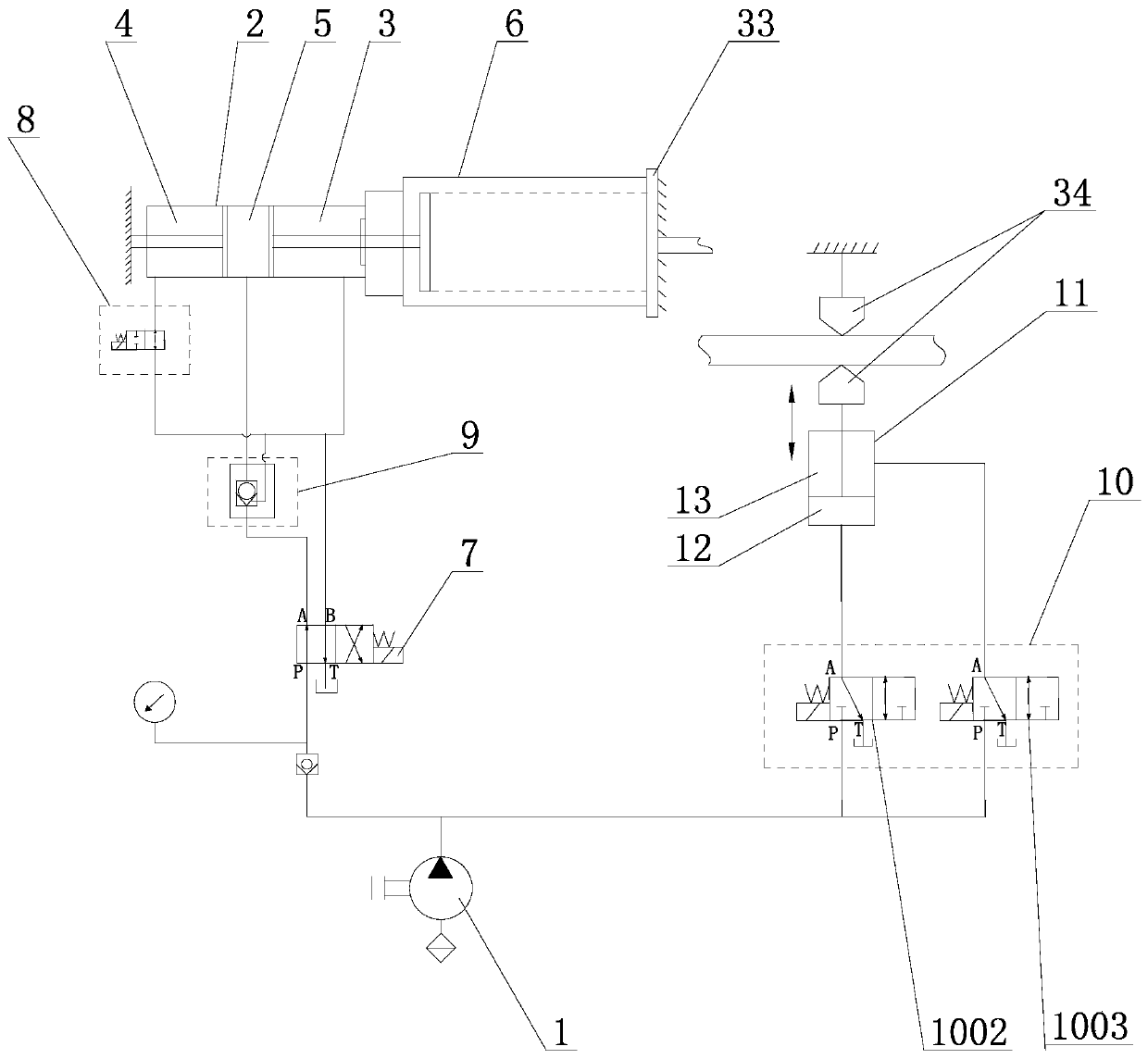
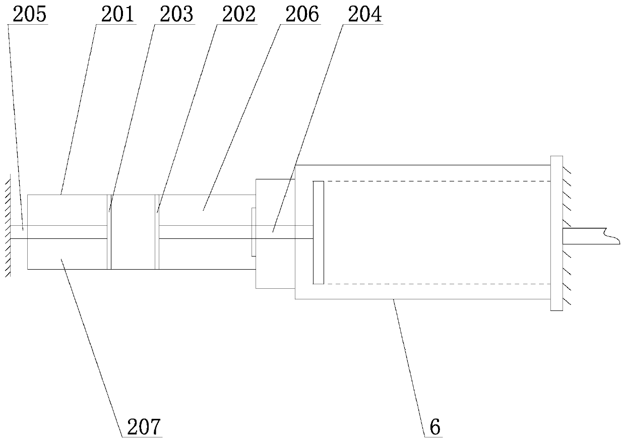
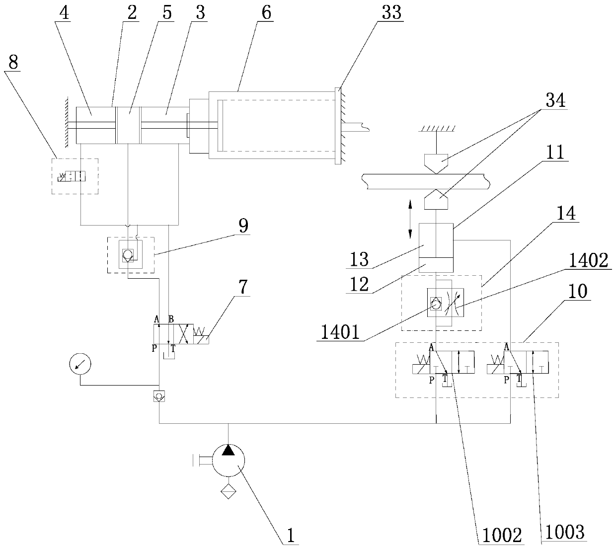
The invention relates to a glue-leakage prevention hydraulic system for a butyl rubber coating machine and an integrated valve block of the glue-leakage prevention hydraulic system. An oil pump, a double-rod hydraulic cylinder and a glue squeezing oil circuit, wherein the oil pump is used for providing a hydraulic power source for the hydraulic system; the double-rod hydraulic cylinder is used asa glue cylinder and a glue changing ejecting cylinder, the glue cylinder and the glue changing ejecting cylinder share a rodless cavity A, and the glue cylinder is connected to a glue barrel; the gluesqueezing oil circuit comprises a main control electromagnetic reversing valve A, and the oil pump is connected with the double-rod hydraulic cylinder through the main control electromagnetic reversing valve A, a delay solenoid valve for adjusting the cylinder-glue ration to enable the glue changing ejecting cylinder to return to the cylinder first is arranged on an oil circuit, connected with the main control electromagnetic reversing valve A, of a rod cavity B of the glue changing ejecting cylinder, and a hydraulic control check valve is arranged on an oil circuit, connected with the main control electromagnetic reversing valve A, of the rodless cavity A. The technical problems of glue leakage and uneven glue application during glue changing can be effectively solved, meanwhile, the hydraulic control system is highly integrated, occupies a small space and is easy to control.

Description

Technical field: [0001] The invention relates to the technical field of the hydraulic system of a butyl rubber coating machine, in particular to a hydraulic system with no leakage of glue during glue replacement and good pressure maintaining effect, and at the same time, the electromagnetic valves in the hydraulic system are integrated and designed. Background technique: [0002] Butyl glue coating machine is an indispensable CNC processing equipment in the production of insulating glass doors and windows. Its main function is to apply butyl glue evenly on both sides of the aluminum spacer. After the glue is applied, the glass is installed on the Both sides of the aluminum spacer, and then realize the first seal of the groove aluminum type insulating glass doors and windows. The main structure of the existing butyl rubber coating machine includes a frame. A transmission mechanism is arranged on the frame. The two sides of the transmission mechanism are provided with pressing...

Claims


Application Information

Patent Timeline
Patent Type & Authority Applications(China)
IPC IPC(8): B05C5/02B05C11/10F15B11/16F15B13/06
CPCB05C5/02B05C11/1026B05C11/1036F15B11/16F15B13/06
Inventor 王小钊
Owner 济南悉通液压设备配套有限公司
Why Eureka
Eureka Blog
Learn More