
Metal abrasive processing technology

A processing technology and metal abrasive technology, which is applied in the field of metal abrasive processing technology, can solve the problems of reduced pellet cutting quality and production efficiency, fast cutting knife wear, energy waste, etc., and achieves small impact vibration, reduced failure rate, and reduced wasteful effect

Inactive Publication Date: 2020-08-14
王认认
View PDF0 Cites 1 Cited by
  • Summary
  • Abstract
  • Description
  • Claims
  • Application Information

AI Technical Summary

Problems solved by technology

In the existing steel wire shot cutting technology, since the steel wires are cut row by row, the output power of the motor needs to exceed the minimum power for a row of steel wires to be cut, and the motor needs to choose a high power to increase the cost. Driven by the drive, the steel wire is cut intermittently. Even when the steel wire is not being cut, the motor is still running at high power, and energy is wasted. In addition, when the cutter cuts the steel wire, one edge of the cutter always acts on the steel wire, causing friction. A lot of heat, the cutter wears fast, and the cutter needs to be replaced frequently, resulting in a decrease in the quality and production efficiency of the pellet cutting

Method used


Image

  • Metal abrasive processing technology
  • Metal abrasive processing technology
  • Metal abrasive processing technology

Examples


Embodiment Construction

[0029] The embodiments of the present invention will be described in detail below with reference to the accompanying drawings, but the present invention can be implemented in many different ways defined and covered by the claims.

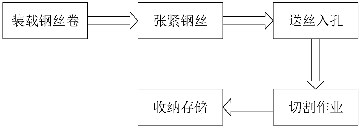
[0030] like Figure 1 to Figure 5 Shown, a kind of metal abrasive processing technology, comprises the following steps:

[0031] Step 1. Loading steel wire coils: take a plurality of wire feeding reels 11 wound with steel wires, install them on wire winding posts respectively and arrange them in a row;

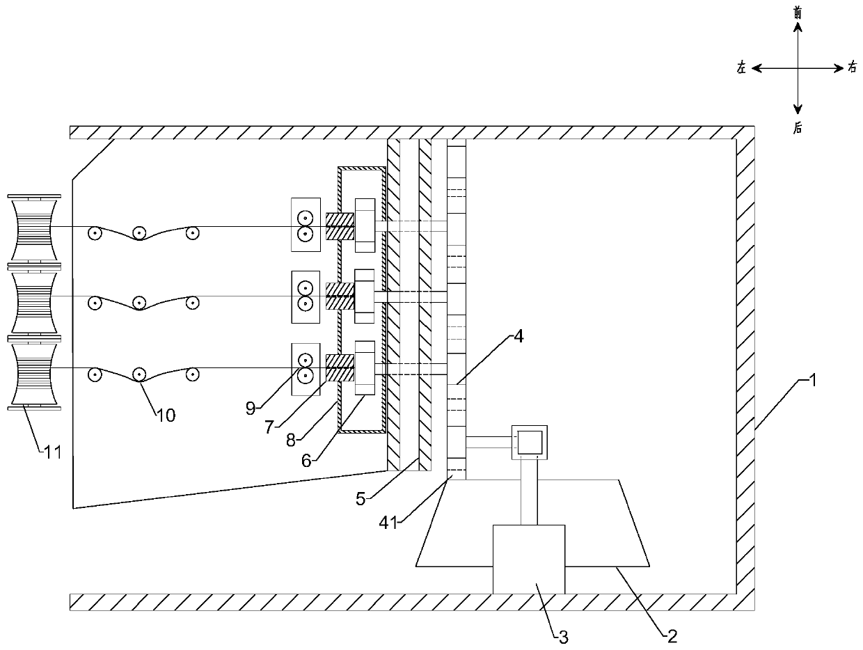
[0032] Step 2. Tensioning the steel wire: pull out the steel wire on the wire feeding wheel 11, make the steel wire go around the tensioning wheel 10 in turn, and connect to the wire feeding device 9, and the wire feeding device 9 uses power to pull the steel wire to tension the steel wire;

[0033] Step 3, feeding the wire into the hole: after the motor of the wire feeding device 9 is started, the steel wire is pulled into the through hole of the ...


PUM


Abstract

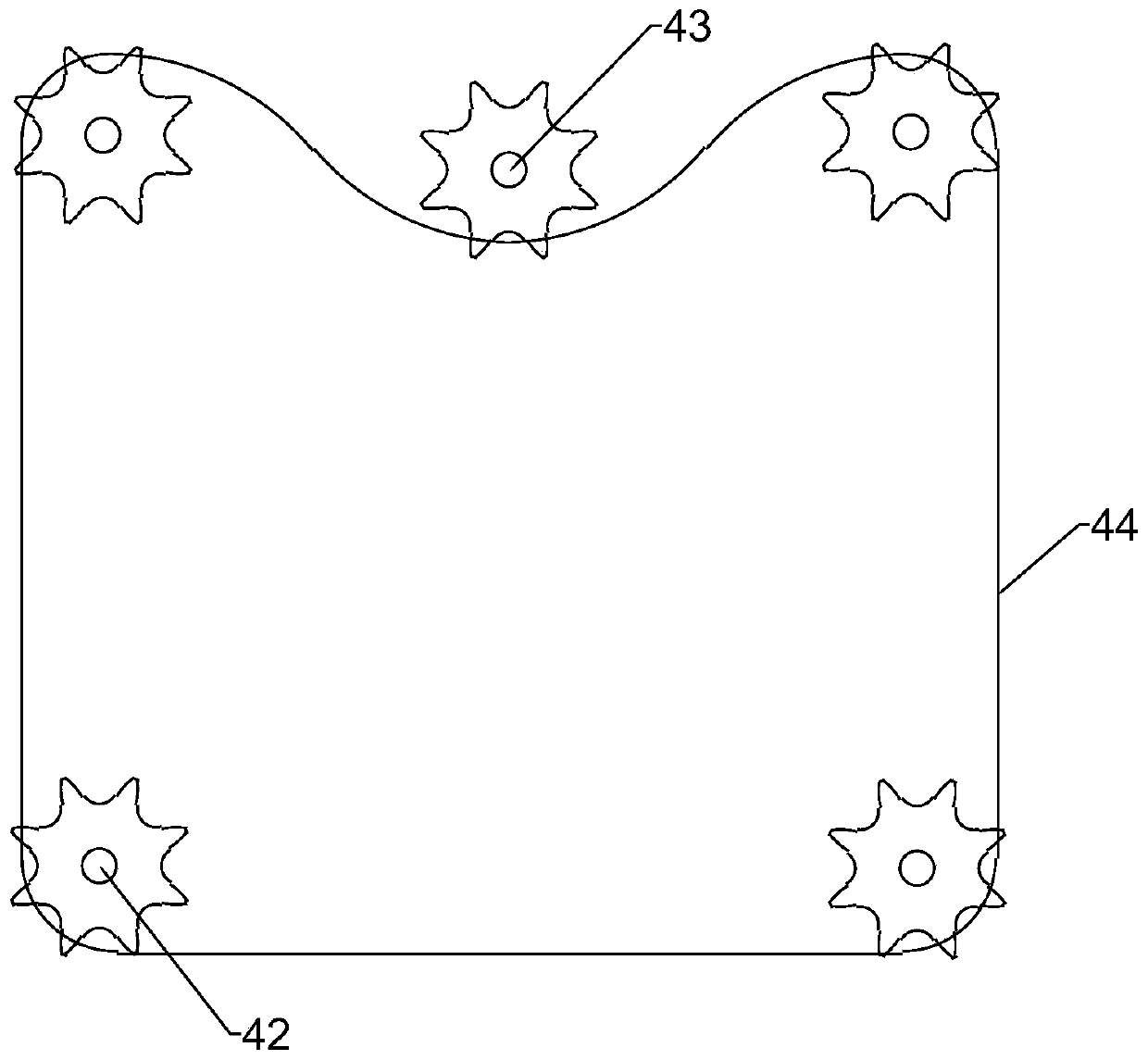
The invention relates to the processing field of metal abrasive, in particular to a metal abrasive processing technology. A device for realizing the metal abrasive processing technology comprises a housing, a base, an electric motor, a transmitting device, a supporting plate, rotary cutters, cutting platforms, a pill loading box, wire transporting devices, tensioning wheels and wire supporting wheels, wherein the base is arranged in the housing; the electric motor is mounted on the base; the transmitting device is arranged on the base; each rotary cutter penetrates through a corresponding through hole in the supporting plate to be linked to a corresponding chain wheel of the transmitting device; and a steel wire on each wire supplying wheel sequentially penetrates through the correspondingtensioning wheel, the corresponding wire transporting device and the corresponding cutting platform. According to the metal abrasive processing technology disclosed by the invention, the rotary cutters are arranged, so that integrated one-time cutting of steel wires is replaced by single repeated dispersing cutting, so that time for cutting the steel wires by the rotary cutters is dispersed, thepower of the electric motor is effectively used, impact vibration to the cutters is small, the structural stability of the movable connecting parts of the cutters is improved, and the failure rate isreduced.

Description

technical field [0001] The invention relates to the field of metal abrasive processing, in particular to a metal abrasive processing technology. Background technique [0002] Metal abrasives are widely used in the process of mechanical processing, and the most commonly used metal abrasives are steel wire cut shot, which is made by cutting steel wire with a machine, and is a necessity for shot blasting equipment, shot blasting equipment and sandblasting equipment. Widely used in machinery, casting, and shipbuilding industries, its function is to remove sand and rust, remove oxidation, and strengthen molding. In the existing steel wire shot cutting technology, since the steel wires are cut row by row, the output power of the motor needs to exceed the minimum power for a row of steel wires to be cut, and the motor needs to choose a high power to increase the cost. Driven by the drive, the steel wire is cut intermittently. Even when the steel wire is not being cut, the motor is...

Claims


Application Information

Patent Timeline
Patent Type & Authority Applications(China)
IPC IPC(8): B21F11/00
CPCB21F11/00
Inventor 王认认
Owner 王认认
Learn More