High-temperature heating device for bearings

A high-temperature heating and bearing technology, which is applied in metal processing, metal processing equipment, manufacturing tools, etc., can solve the problems of difficult bearing heating, difficulty in fully cleaning residual oil, etc., and achieves the effect of uniform heating and good recycling

Active Publication Date: 2020-08-14
苏州琦谷佳科技有限公司
View PDF10 Cites 0 Cited by
  • Summary
  • Abstract
  • Description
  • Claims
  • Application Information

AI Technical Summary

Problems solved by technology

[0005] In order to overcome the disadvantages in the prior art that it is difficult to fully clean the remaining oil and evenly heat the bearing when installing the bearing, the technical problem to be solved is: to provide a bearing that can fully clean the remaining oil and uniformly heat the bearing High temperature heating device

Method used


Image

  • High-temperature heating device for bearings
  • High-temperature heating device for bearings
  • High-temperature heating device for bearings

Examples


Embodiment 1

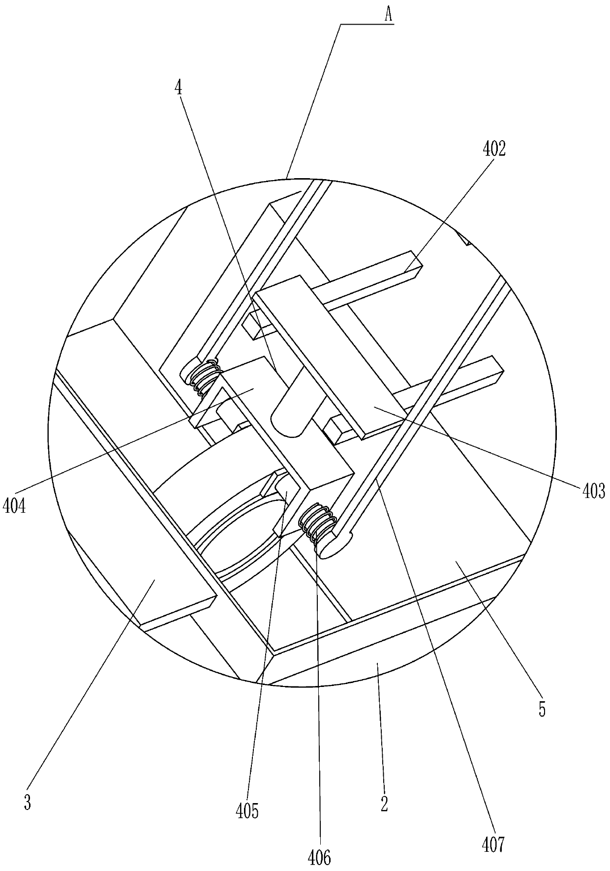
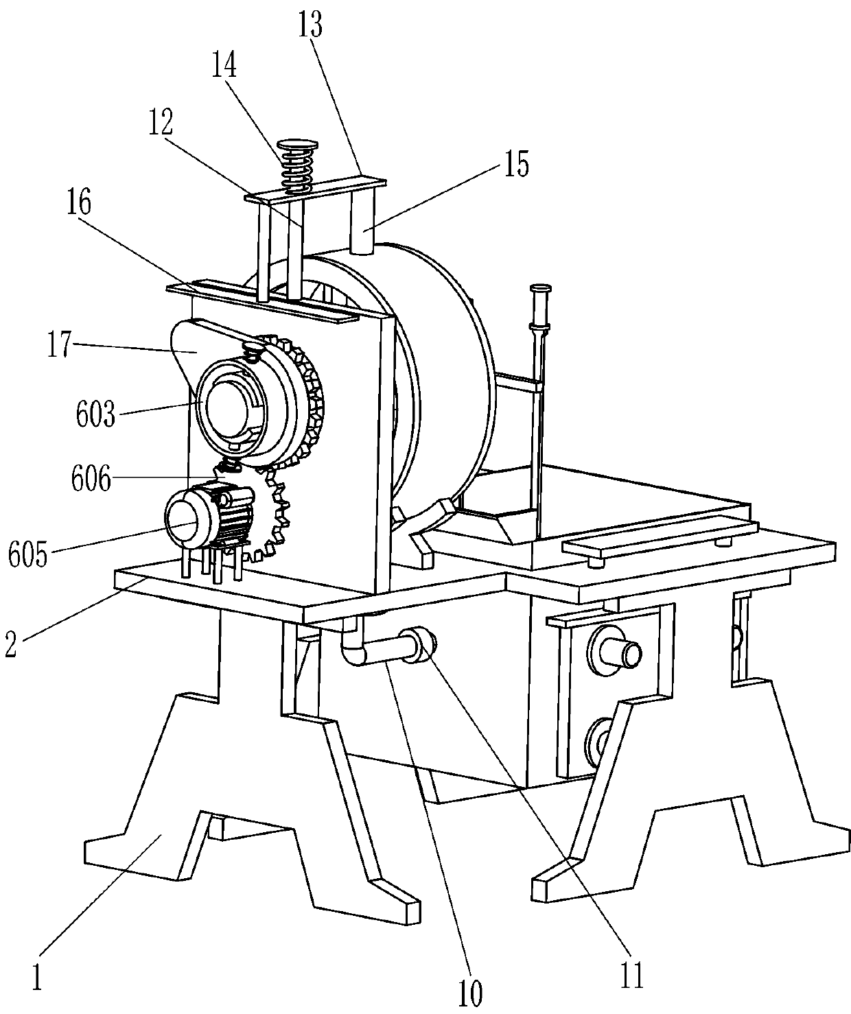
[0023] A bearing high temperature heating device, such as Figure 1-5 As shown, it includes a support plate 1, a mounting plate 2, a large oil frame 3, a clamping and placing device 4, a heater 5, a rotating oil throwing device 6, a support block 7, an oil collecting frame 8, a guide sleeve 9, and an oil return pipe 10 and a check valve 11, a mounting plate 2 is installed on the top of the support plate 1, a large oil frame 3 is welded on the left side of the mounting plate 2, a clamping and placing device 4 is provided on the inner front wall of the large oil frame 3, and a large oil frame 3 is provided with Heater 5, the top of the right side of the mounting plate 2 is provided with a rotary oil throwing device 6, and the top of the right side of the mounting plate 2 is provided with two support blocks 7, the support blocks 7 are located between the large oil frame 3 and the rotary oil throwing device 6, supporting An oil collection frame 8 is installed on the block 7, a gui...

Embodiment 2

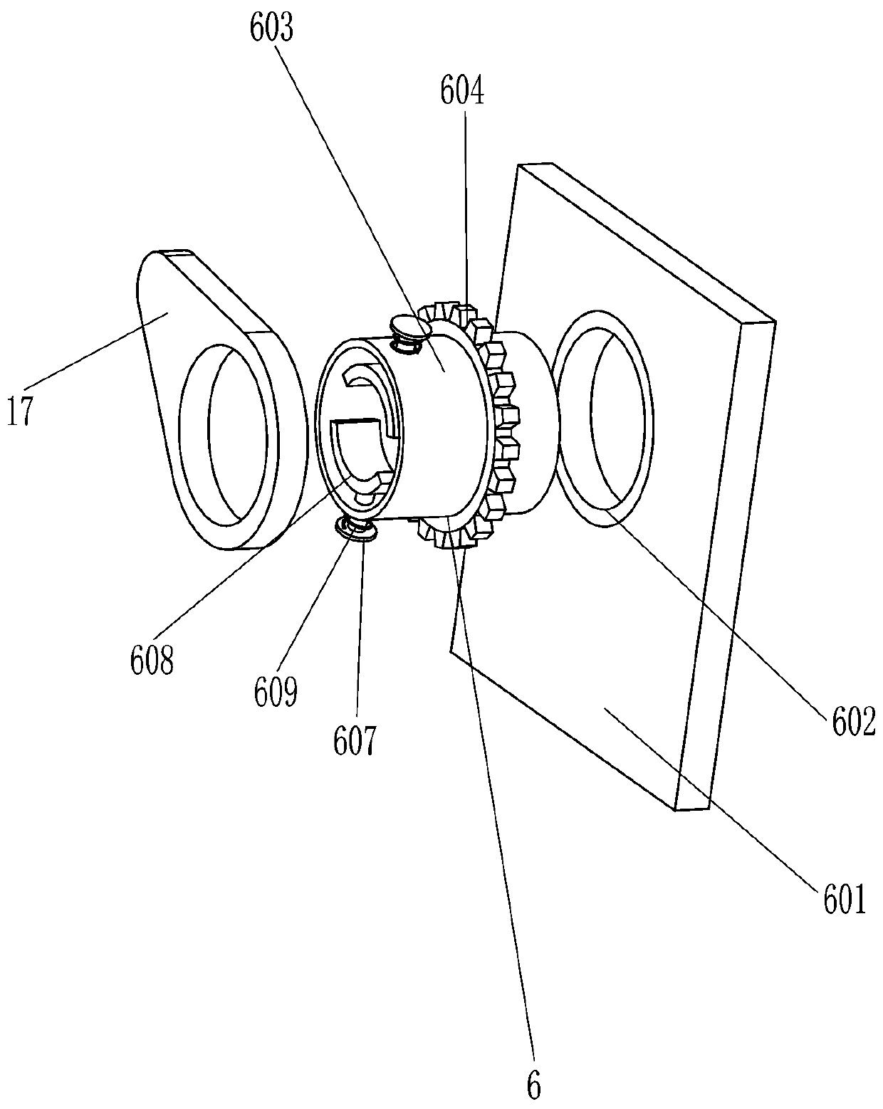
[0030] On the basis of Example 1, such as Figure 1-3 Shown, also comprise guide rod 12, slide plate 13, the 3rd compression spring 14, rubber rod 15, push plate 16 and cam 17, riser 601 tops are connected with guide rod 12 by bolt, slide type is set on guide rod 12 There is a sliding plate 13, a third compression spring 14 is set on the upper part of the guide rod 12, the upper end of the third compression spring 14 is connected with the guide rod 12, the lower end of the third compression spring 14 is connected with the sliding plate 13, and the bottom of the left side of the sliding plate 13 is provided with a rubber Rod 15, rubber rod 15 are in contact with the outside of the oil collecting frame 8, the bottom right side of the sliding plate 13 is provided with a push plate 16, and the outside of the rotating tube 603 is provided with a cam 17, and the cam 17 is in contact with the push plate 16.

[0031] Also includes a return frame 18, the right side of the large oil fra...


PUM


Abstract

The invention relates to a heating device, in particular to a high-temperature heating device for bearings, and aims to provide the high-temperature heating device which is used for the bearings, canclean oil contamination sufficiently and can heat the bearings uniformly. The high-temperature heating device for the bearings comprises at least three supporting plates, a mounting plate mounted at the tops of the supporting plates, a large oil box welded on one side of the mounting plate and used for placing a lot of oil as well as a clamping and placing device arranged on one side of the insideof the large oil box and used for clamping the bearings. According to the heating device, the effects of cleaning the oil contamination sufficiently and heating the bearings uniformly are achieved; and the whole bearings are located inside the oil inside the large oil box and are heated by all the oil, so that the bearings can be heated uniformly.

Description

technical field [0001] The invention relates to a heating device, in particular to a bearing high temperature heating device. Background technique [0002] Bearings are an important part of modern mechanical equipment. The connection between the shaft and the bearing is generally an interference fit. When the bearing is heated until the inner ring expands, the bearing can be easily inserted into the shaft. After the bearing cools down and shrinks, the bearing can be made The shaft and the bearing are only combined together. The existing technology generally heats the bearing through an oil furnace, an oven and an induction heater. Compared with the oil furnace, the other two methods have uneven heating of the bearing, which may affect the assembly of the bearing. . [0003] Existing bearing heating devices, such as a Chinese patent whose patent notification number is CN105397408A discloses an automatic oil cleaning multi-size bearing heating device, which includes a bearing...

Claims


Application Information

Patent Timeline
IPC IPC(8): B23P11/02
CPCB23P11/025
Inventor 钟万杰
Owner 苏州琦谷佳科技有限公司
Why Eureka
Try Eureka