
An automatic processing system for rubber manufacturing

A processing system and rubber technology, applied in the field of rubber manufacturing and processing, to achieve the effect of improving production efficiency and avoiding damage

Active Publication Date: 2021-07-09
杭州美联塑胶有限公司
View PDF0 Cites 0 Cited by
  • Summary
  • Abstract
  • Description
  • Claims
  • Application Information

AI Technical Summary

Problems solved by technology

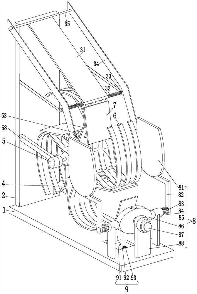
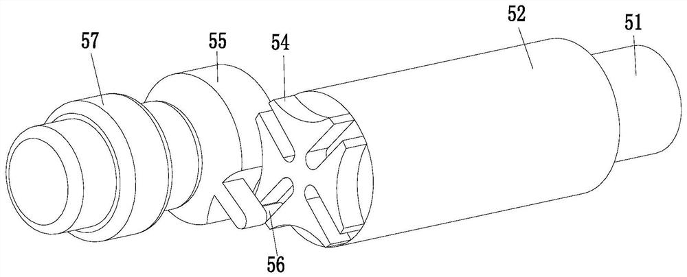
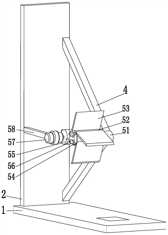
[0008] In order to solve the above problems, the present invention provides an automatic processing system for rubber manufacturing, which includes a bottom plate, a side vertical plate, a guide mechanism, a V-shaped frame, a driving mechanism, a U-shaped frame, a guide plate, a positive position mechanism and an auxiliary mechanism. A rectangular groove is provided on the upper end surface of the side, a side vertical plate is installed at the rear end of the bottom plate, a guiding mechanism is installed on the top of the side vertical plate, the rear end of the V-shaped frame is installed on the front end of the side vertical plate, and a driving mechanism is installed at the front end of the V-shaped frame. Four U-shaped frames are evenly installed on the outside of the driving mechanism by welding. The left end of the U-shaped frame in the counterclockwise direction is installed with a guide plate by welding. Installed on the top surface of the bottom plate, the auxiliary mechanism is installed in the rectangular groove on the bottom plate, and the auxiliary mechanism is located between the lower end of the positive position mechanism and the U-shaped frame at the lower end of the driving mechanism; the invention can collect the cut rubber rods, and It can quickly correct the position of the collected rubber rods. First, the rubber rods roll down along the guide mechanism and fall into the inside of the U-shaped frame through the guide plate. The guide mechanism can guide the rubber rods to prevent the rubber rods from falling freely. damage, so that the rubber rod can slide smoothly into the U-shaped frame, when the U-shaped frame is at the upper end of the driving mechanism, it is at the preparatory station, when the U-shaped frame is at the front end of the driving The lower end is at the take-out position, and then the positive position mechanism corrects the position of the rubber rods in the U-shaped frame. When the rubber rods in the U-shaped frame collect a certain amount, the driving mechanism drives the U-shaped frame to perform intermittent 90-degree positioning rotation , so that the U-shaped frame that was originally located at the preparatory station rotates to the collection station, thereby continuing to collect the rubber rods, and the U-shaped frame that was originally located at the collection station rotates to the removal station, so that the collected rubber rods can be manually Bundling and taking out, the cooperation of the U-shaped frame and the driving mechanism can quickly take out the collected rubber rods without shutting down the assembly line, which improves the collection efficiency and transfer efficiency of the rubber rods, and the auxiliary mechanism can prevent the rubber rods from falling in the U Falling off when the frame is turned

Method used


Image

  • An automatic processing system for rubber manufacturing
  • An automatic processing system for rubber manufacturing
  • An automatic processing system for rubber manufacturing

Examples


Embodiment Construction

[0026] In order to make the technical means, creative features, goals and effects achieved by the present invention easy to understand, the present invention will be further described below in conjunction with specific illustrations. It should be noted that, in the case of no conflict, the embodiments in the present application and the features in the embodiments can be combined with each other.

[0027] Such as Figure 1 to Figure 3As shown, an automatic processing system for rubber manufacturing, in order to solve the above problems, the present invention provides an automatic processing system for rubber manufacturing, including a bottom plate 1, a side vertical plate 2, a guide mechanism 3, a V-shaped frame, and a driving mechanism 5 , U-shaped frame 6, guide plate 7, positive position mechanism 8 and auxiliary mechanism 9, a rectangular groove is arranged on the upper end surface of the front side of the bottom plate 1, a side riser 2 is installed on the rear end of the b...


PUM


Abstract

The invention relates to an automatic processing system for rubber manufacturing, which includes a bottom plate, a side vertical plate, a guide mechanism, a V-shaped frame, a driving mechanism, a U-shaped frame, a guide plate, a positive position mechanism and an auxiliary mechanism. The rear end of the bottom plate is equipped with a side vertical plate, the top of the side vertical plate is equipped with a guide mechanism, the rear end of the V-shaped frame is installed on the front surface of the side vertical plate, the front end of the V-shaped frame is installed with a driving mechanism, and the outside of the driving mechanism is evenly installed. Four U-shaped frames, the left end of the U-shaped frame in the counterclockwise direction is equipped with a guide plate, and the front end of the U-shaped frame located at the front end of the driving mechanism is provided with a positive position mechanism. The lower end of the positive position mechanism is installed on the upper surface of the bottom plate, and the auxiliary mechanism is installed on the bottom plate In the rectangular groove; the present invention can solve the problem of the existing rubber rod production: when the rubber rod falls into the storage box, it is easy to damage and pop out of the storage box; the rubber rod is messy after falling into the storage box; Sticks are replaced with empty boxes.

Description

technical field [0001] The invention relates to the field of rubber manufacturing and processing, in particular to an automatic processing system for rubber manufacturing. Background technique [0002] Rubber refers to a highly elastic polymer material with reversible deformation, and rubber is divided into two types: natural rubber and synthetic rubber. Rubber rods are an application method of rubber. The processing processes of different types of rubber rods are also different. There are The rubber rods need to be cut into segments, so after the rubber rods are cut, they need to be sorted out. [0003] In the prior art, after the rubber rods are cut, the rubber rods fall freely in the storage box, and then they are placed neatly manually, and after the rubber rods in the storage box are full, the assembly line needs to be suspended to prevent the rubber rods from falling into the storage box. On the ground, workers need to quickly replace the storage boxes with empty ones...

Claims


Application Information

Patent Timeline
Patent Type & Authority Patents(China)
IPC IPC(8): B65B35/58B65B27/10
CPCB65B27/10B65B35/58
Inventor 荣文龙范文祥
Owner 杭州美联塑胶有限公司
Learn More