Automatic workpiece feeding mechanism

A technology of feeding mechanism and feeding mechanism, which is applied in the field of parts processing, can solve problems such as difficult control and maintenance, decreased work efficiency, and difficult stable feeding, and achieves good market prospects, low cost, and convenient operation.

Active Publication Date: 2020-08-14
浙江省平湖技师学院
View PDF10 Cites 7 Cited by
  • Summary
  • Abstract
  • Description
  • Claims
  • Application Information

AI Technical Summary

Problems solved by technology

[0003] In order to realize the automation of machine tool processing, it is necessary to realize the automation of workpiece loading and unloading. When processing some special-shaped parts and need to have a reference position, it is difficult to use traditional mechanical feeders to achieve accurate and stable feeding. Usually, manipulators are used to feed. , the cost is high, and the control and maintenance are difficult; and during the production process, the workpiece needs to be transported from one processing place to another, and due to the limited length of the conveying device, it is generally removed after the processing is completed, and it needs to be manually transported to the Another processing is very troublesome; moreover, the existing workpiece conveying cannot rotate the workpiece, which leads to a decrease in work efficiency

Method used


Image

  • Automatic workpiece feeding mechanism
  • Automatic workpiece feeding mechanism
  • Automatic workpiece feeding mechanism

Examples


Embodiment

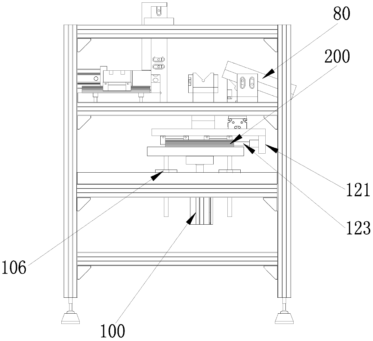
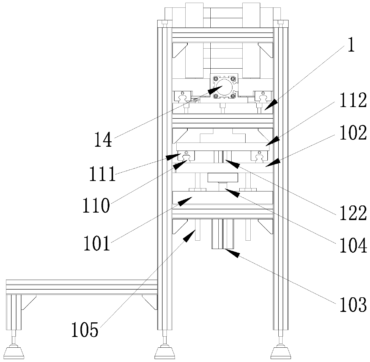
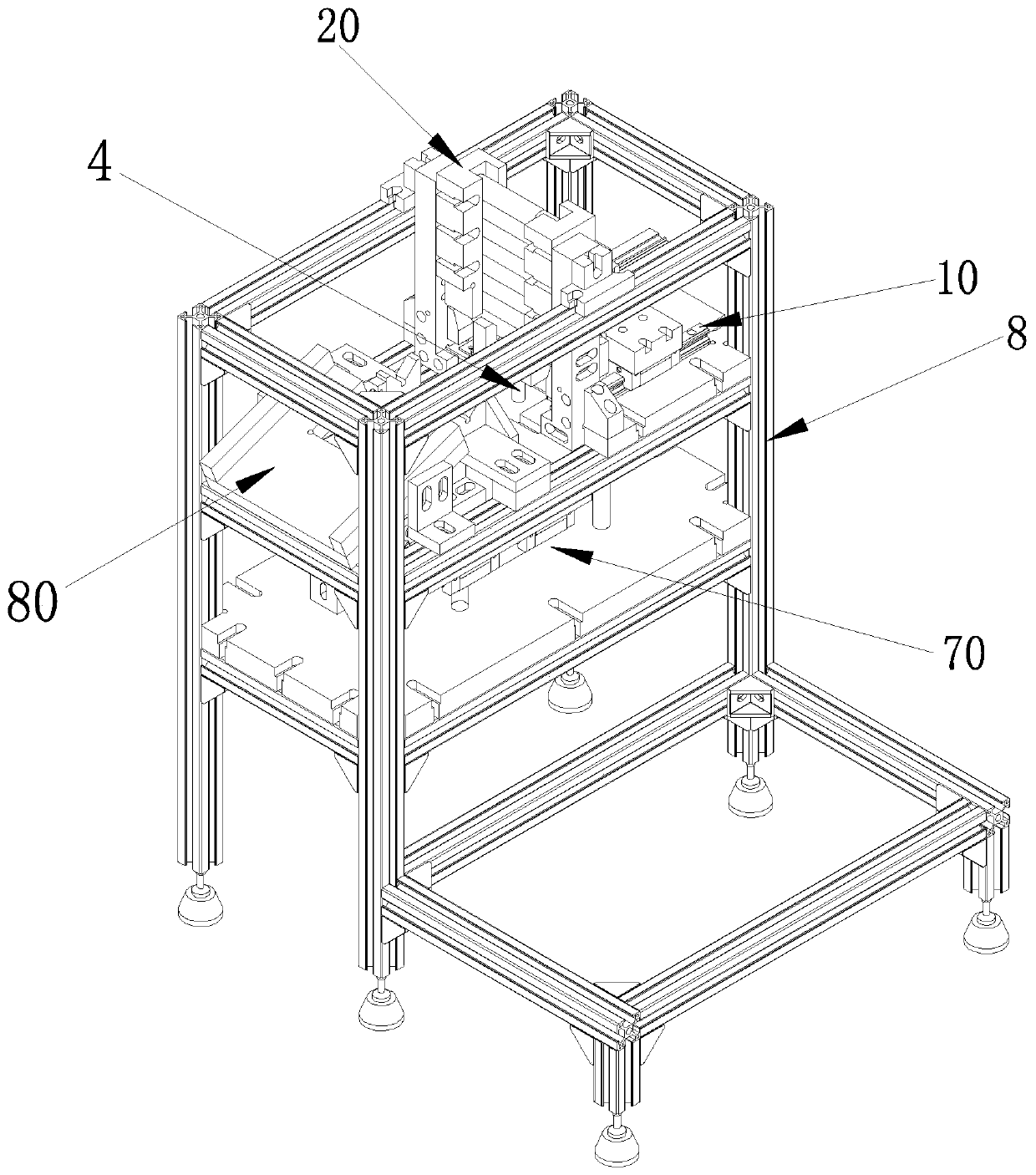
[0048] Such as Figure 1-8 As shown, a kind of automatic workpiece feeding mechanism provided by the present embodiment includes a frame 8, a feeding mechanism 20, a feeding device 40, a material receiving mobile device 70 and a material discharging mechanism 80; the feeding mechanism 20, the feeding device 40, the receiving device The material moving device 70 and the discharging mechanism 80 are assembled on the frame 8; the feeding mechanism 20 is located on the feeding device 40; On the frame 8; the pushing device 10 includes a conveying slide rail 11 fixed on the base plate 1 and arranged symmetrically along the length direction of the base plate 1, a slide block 12 is slidably mounted on the transport slide rail 11, and a slide block 12 is fixed on the slide block 12. There is a product fixture 30 for placing workpieces. The rear end of the product fixture 30 is connected with a drive mechanism 14. The drive mechanism 14 is fixed on the bottom plate 1. The drive mechanis...


PUM


Abstract

The invention relates to an automatic workpiece feeding mechanism. The automatic workpiece feeding mechanism comprises a rack, an inlet mechanism, a feeding device, a receiving and moving device and adischarging mechanism; the feeding device comprises a bottom plate and a pushing device fixedly arranged on the bottom plate; the bottom plate is fixedly arranged on the rack; the pushing device comprises conveying sliding rails which are fixedly arranged on the bottom plate and are symmetrically distributed in the length direction of the bottom plate; sliding blocks are glidingly assembled on the conveying sliding rails; a product jig for placing a workpiece is fixedly arranged on the sliding blocks; the back end of the product jig is connected with a driving mechanism; and the driving mechanism is fixedly arranged on the bottom plate, drives the product jig to slide forwards and backwards and is used for pushing the workpiece inside the product jig. The automatic workpiece feeding mechanism can be widely applied to accurate taking of sequentially and vertically stacked materials from many materials to the sole material, discharging is performed when a driving motor pushes out, supplementing is performed when the driving motor returns, sequential circulation can be realized, stepping feeding can be realized, and the automatic workpiece feeding mechanism has the advantages of simple structure, convenience in operation and low cost and has the good market prospects.

Description

technical field [0001] The invention belongs to the technical field of parts processing, and in particular relates to an automatic workpiece feeding mechanism. Background technique [0002] With the development of production, the competition in the processing field is becoming increasingly fierce, and it has become an inevitable trend to improve quality and reduce costs. An important means of reducing costs is to increase the level of automation. [0003] In order to realize the automation of machine tool processing, it is necessary to realize the automation of workpiece loading and unloading. When processing some special-shaped parts and need to have a reference position, it is difficult to use traditional mechanical feeders to achieve accurate and stable feeding. Usually, manipulators are used to feed. , the cost is high, and the control and maintenance are difficult; and during the production process, the workpiece needs to be transported from one processing place to anot...

Claims


Application Information

Patent Timeline
Patent Type & Authority Applications(China)
IPC IPC(8): B65G47/06B65G25/02
CPCB65G47/06B65G25/02
Inventor 张杰张邹伟蒋斌
Owner 浙江省平湖技师学院
Why Eureka
Try Eureka