
Bar spacer, and water-stop belt installing structure and burying method

A technology for installing structure and positioning card, which is applied in mining equipment, shaft equipment, earth-moving drilling, etc., can solve the problems of incompact concrete pouring, consume a lot of manpower and time, and troublesome operation, and prevent water seepage at the circumferential construction joints. , Improve production efficiency, simple and convenient operation

Pending Publication Date: 2020-08-14
中铁二十二局集团市政工程有限公司
View PDF0 Cites 1 Cited by
  • Summary
  • Abstract
  • Description
  • Claims
  • Application Information

AI Technical Summary

Problems solved by technology

[0004] At present, the method of fixing and directly adopting steel end molds to fix the waterstop by positioning steel bars and adding flat irons has the following problems: (1) the method of using positioning steel bars to add flat irons is cumbersome to operate, the process is complicated, and it consumes a lot of manpower and time. When disassembling the flat iron after pouring the concrete, the bolts for reinforcing the flat iron are easily stuck by the formwork, which consumes a lot of materials during disassembly, and will damage the appearance and waterstop of the finished lining, affecting the appearance and waterproofing; (2) Directly use steel end mold clamps The water-stop method of the water-stop method is not smooth and not centered, which seriously affects the appearance; (3) in the above two methods, the water-stop is easy to bend and wrinkle during the pouring process, and the air extrusion causes the concrete pouring to be not densely formed. The back of the lining is empty, resulting in quality defects, further causing the concrete pouring to be not dense, causing water seepage at the circumferential construction joints, and water return at the inverted arch construction joints

Method used


Image

  • Bar spacer, and water-stop belt installing structure and burying method
  • Bar spacer, and water-stop belt installing structure and burying method
  • Bar spacer, and water-stop belt installing structure and burying method

Examples


Embodiment Construction

[0031] The specific implementation manners of the present invention will be further described in detail below in conjunction with the accompanying drawings and embodiments. The following examples are used to illustrate the present invention, but are not intended to limit the scope of the present invention.

[0032] In the description of the present invention, it should be understood that the orientation or positional relationship indicated by the terms "upper", "lower", "left", "right", "top", "bottom" etc. Orientation or positional relationship is only for the convenience of describing the present invention and simplifying the description, and does not indicate or imply that the referred device or element must have a specific orientation, be constructed and operated in a specific orientation, and thus should not be construed as a limitation of the present invention. It should be understood that the terms "first", "second", etc. are used in the present invention to describe va...


PUM


Abstract

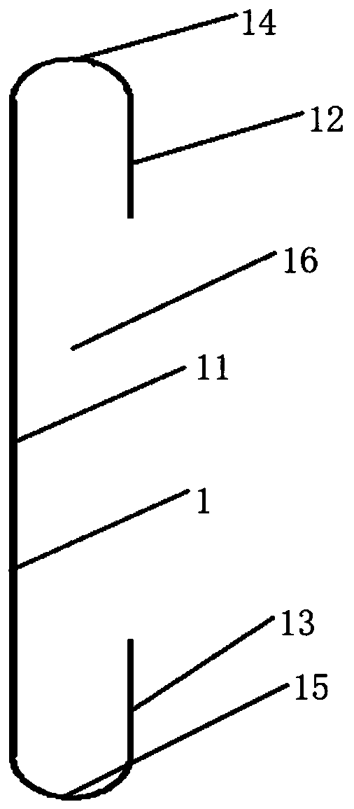
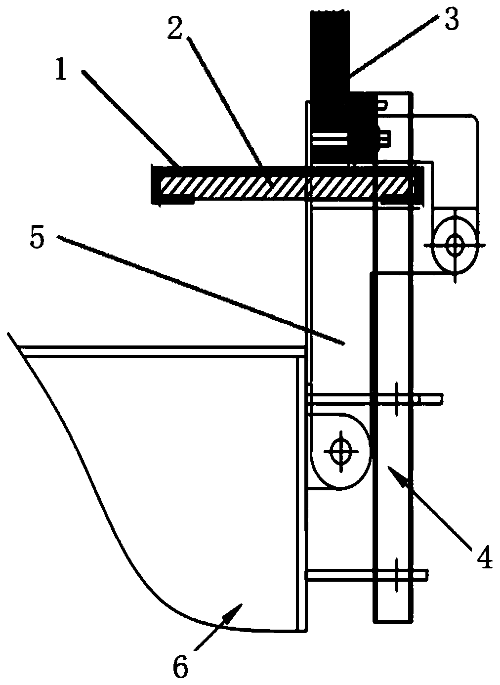
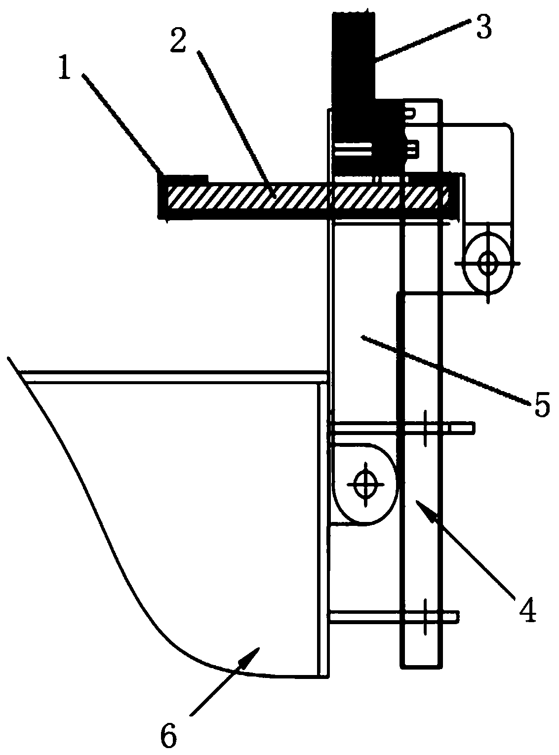
The invention discloses a bar spacer, and a water-stop belt installing structure and burying method. The bar spacer comprises a body, a first hook edge and a second hook edge, wherein the first hook edge and the second hook edge are parallel to the body and arranged in a spaced mode; the first hook edge is connected to the top end of the body through a first transition arc, and the second hook edge is connected to the bottom end of the body through a second transition arc; the body, the first hook edge, the second hook edge, the first transition arc and the second transition arc form a clamping groove which is used for clamping a water-stop belt in a matched mode; and a lower mold abuts against one side of the clamping groove, and an upper mold is arranged on the other side of the clampinggroove. According to the bar spacer, and the water-stop belt installing structure and burying method, one-time forming of the water-stop belt can be ensured, lining of a finished product and the water-stop belt are not damaged, the situation that concrete is not compact due to the fact that the water-stop belt is corrugated and bent is avoided, water leakage of an annular construction joint is effectively prevented, and the inverted arch construction joint water returning problem is solved; and the construction technology is optimized, a more humanized construction method is created, the production efficiency is improved, and the construction cost is controlled.

Description

technical field [0001] The invention relates to the technical field of lining construction in underground tunnel engineering, in particular to a positioning card, a waterstop installation structure and an embedding method. Background technique [0002] Highway and railway tunnels are often constructed using the new Austrian method, that is, after excavation, the excavation surface of the tunnel is firstly supported, then the inverted arch is poured, and finally the secondary lining trolley is arranged in the tunnel to pour the secondary lining. Due to the limited length of the secondary lining trolley, the secondary lining of the tunnel is poured in sections, which causes gaps between the two adjacent sections of concrete, which are prone to water leakage. The current practice is to set up a buried waterstop between two sections of concrete. [0003] There are two methods for fixing buried waterstops in tunnels in the prior art: 1. The fixing method of buried rubber waterst...

Claims


Application Information

Patent Timeline
IPC IPC(8): E21D11/38
CPCE21D11/381E21D11/385
Inventor 曾祥记王冠英张金龙强鹏敏姚日高邸立建王宏亮冯博李强岳光茂谢盛董德玲李旭
Owner 中铁二十二局集团市政工程有限公司
Learn More