

Automatic measuring device and method for inner wall of cavity part
A technology for measuring devices and components, applied in measuring devices, optical devices, instruments, etc., can solve problems such as measurement difficulties, limited internal space of cavity parts, difficulty in sticking and removing marking points, etc., and achieve the effect of simplifying calculations
- Summary
- Abstract
- Description
- Claims
- Application Information
AI Technical Summary
Problems solved by technology
Method used
Image

Examples
Embodiment 1
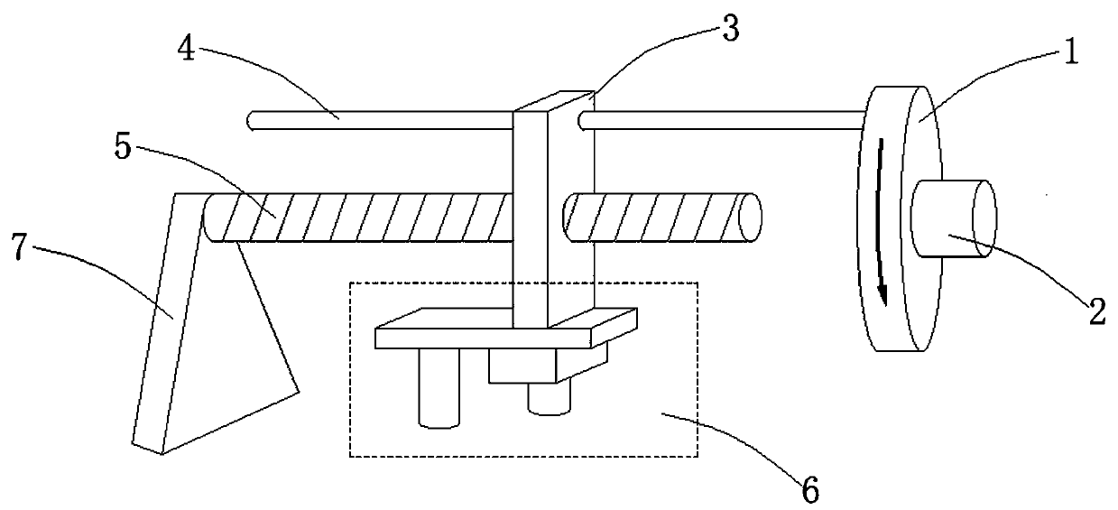
[0032] The main structure of this embodiment, such as figure 1 As shown, it includes a screw-in mechanism and a lead screw 5. The screw-in mechanism is threadedly connected with the lead screw 5. One end of the screw-in mechanism is provided with a driver 1 and the other end is fixedly connected with a support frame 7. The driver 1 can drive the screw-in mechanism. Rotate on the lead screw 5 to make it move along the axial direction of the lead screw 5, the lower part of the screw-in mechanism is provided with a visual measurement mechanism 6; the driver 1 is also equipped with an encoder 2, and the encoder 2 and the visual measurement mechanism 6 Electrically connected, the encoder 2 synchronously reflects the rotation of the precession mechanism on the lead screw, and outputs a synchronous pulse signal to the visual measurement mechanism 6, so that the visual measurement mechanism 6 performs visual measurement synchronously.
[0033] Among them, the structure of the tighteni...
Embodiment 2
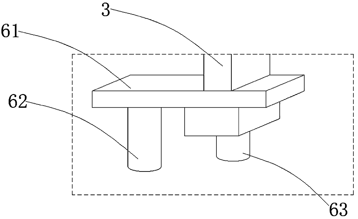
[0046] On the basis of the above-mentioned embodiments, this embodiment further defines a visual measurement device. The visual measurement device includes a projection device and a camera, and their relative positional relationship is known through calibration. According to the difference of the projection device, the visual measurement device can be a point measurement , Line measurement and surface measurement device. Other parts of this embodiment are the same as those of the foregoing embodiment, and will not be repeated here.
[0047] It can be understood that the structure of the measuring device according to an embodiment of the present invention, such as the working principle and working process of components such as the camera 63 and the projection device 62, are all prior art, and are well known to those skilled in the art, and will not be described here. Let's describe it in detail.
PUM
 Abstract
Description
Claims
Application Information