
Screen window small micro-pressure drop testing device based on small wind tunnel

A technology for testing devices and screens, applied in measuring devices, testing of machines/structural components, aerodynamic tests, etc., can solve the problems of high cost of instruments, achieve simple and easy operation, easy disassembly and assembly, and reduce the accuracy of instruments required effect

Active Publication Date: 2020-08-14
SOUTHEAST UNIV
View PDF4 Cites 1 Cited by
  • Summary
  • Abstract
  • Description
  • Claims
  • Application Information

AI Technical Summary

Problems solved by technology

Therefore, the existing screen window pressure drop measurements all rely on high-precision micro-manometers (accuracy ± 0.1Pa), and the instrument cost is relatively high

Method used


Image

  • Screen window small micro-pressure drop testing device based on small wind tunnel
  • Screen window small micro-pressure drop testing device based on small wind tunnel
  • Screen window small micro-pressure drop testing device based on small wind tunnel

Examples


Embodiment 1

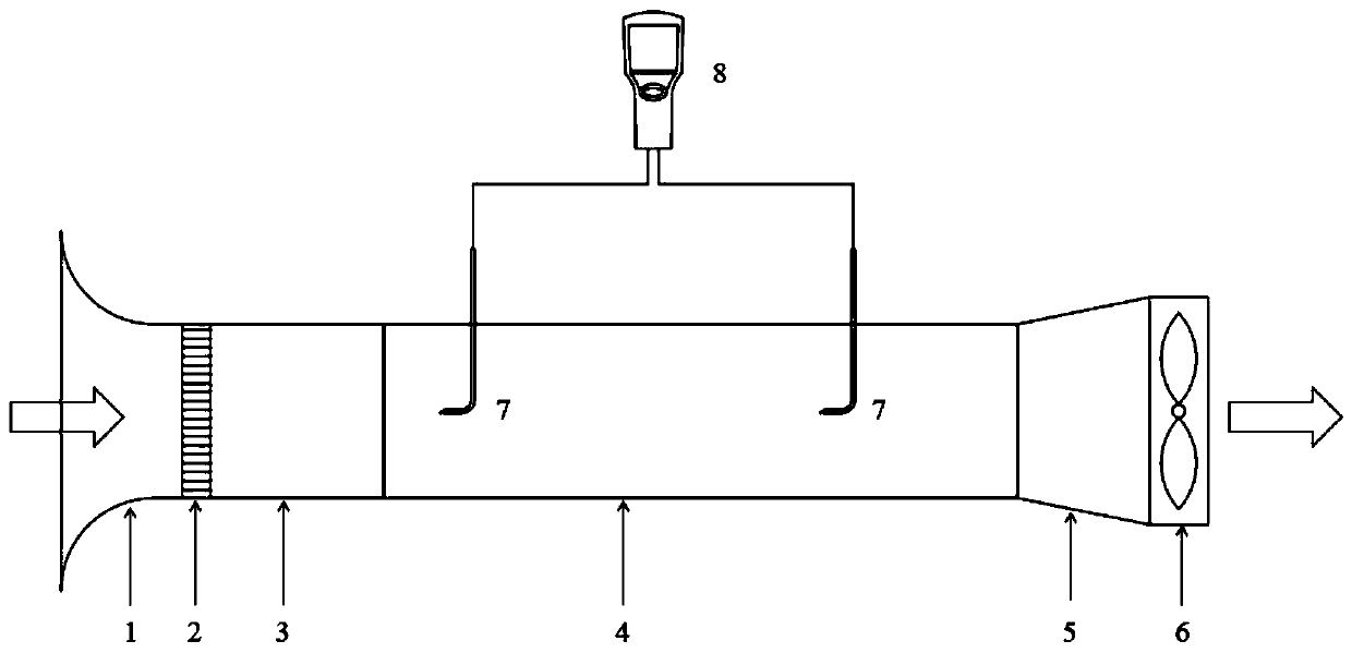
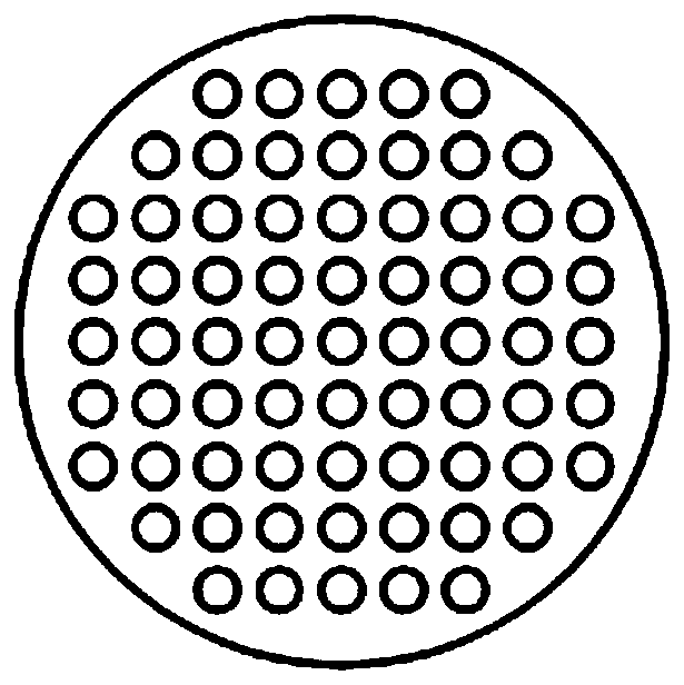
[0025] A small and micro pressure drop test device for screen windows based on a small wind tunnel of the present invention includes an air inlet section, an experimental section and an air outlet section connected in sequence, and the air inlet section includes an inlet section 1, a flow equalization section 2 and a transition section connected in sequence 3. The entrance section 1 is a double-twisted tapered circular air duct, the entrance radius of the entrance section 1 is 0.2m, the exit radius of the entrance section 1 is 0.125m, and the length of the entrance section 1 is 0.2m; figure 2 As shown, the equalizing section 2 is a circular metal equalizing plate, and the diameter of the orifice plate is uniformly distributed with 8mm round holes; the transition section 3 is a cylindrical air duct, the radius of the transition section 3 is 0.125m, and the length of the transition section 3 is 0.2m.

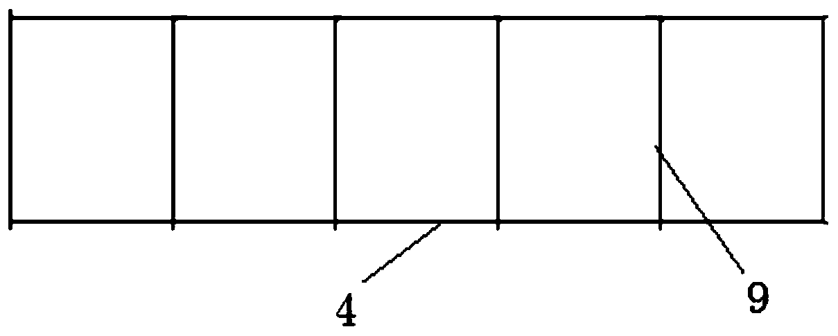
[0026] Such as image 3 with Figure 4 As shown, the experimental section ...

Embodiment 2

[0028] The structure of Example 2 is the same as that of Example 1, except that the length of each cylindrical air duct in the experimental section 4 is 0.2 m.

Embodiment 3

[0030] The structure of Example 3 is the same as that of Example 1, except that the length of each cylindrical air duct in the experimental section 4 is 0.3 m.


PUM


Abstract

The invention discloses a screen window small micro-pressure drop testing device based on a small wind tunnel. The device comprises an air inlet section, an experiment section and an air outlet section which are sequentially communicated. The air inlet section comprises an inlet section, a flow equalizing section and a transition section which are sequentially communicated; the experiment sectioncomprises five sections of cylindrical air pipes which are sequentially communicated, and a screen window is installed between every two adjacent cylindrical air pipes; and the air outlet section comprises an outlet section and a draught fan arranged at the front end of the outlet section; and the experiment section is connected with a handheld hot-wire anemometer through a Pitot tube. The wind pipe is used for simulating a wind tunnel and thus a wind field during natural ventilation of a building is reproduced to the greatest extent, so that a small micro-pressure drop test of the screen window is facilitated; the multiple layers of screen windows are arranged between the adjacent air pipes of the experiment section, the pressure difference passing through the multiple layers of screen windows is measured to reduce the requirement for the precision of the instrument; meanwhile, the wake flow influence passing through the screen windows can be eliminated, so that the experiment resultis more accurate and reliable, and the cost of the experiment instrument is saved.

Description

technical field [0001] The invention relates to a screen window grouting measurement device, in particular to a screen window small and micro pressure drop test device based on a small wind tunnel and a control system thereof. Background technique [0002] Natural ventilation refers to the ventilation method that uses fresh air with a lower outdoor temperature to ventilate and cool industrial and civil buildings under the combined action of heat pressure and wind pressure. It uses natural means to introduce outdoor fresh air through the windows and doors of the building. A ventilation method in which air is used to achieve ventilation. Reasonable natural ventilation can not only make the indoor hot and humid environment meet indoor comfort conditions, improve indoor air quality, but also use natural ventilation technology to effectively achieve passive cooling, which can achieve the purpose of reducing building energy consumption and saving energy. When using natural ventil...

Claims


Application Information

Patent Timeline
Patent Type & Authority Applications(China)
IPC IPC(8): G01M9/00G01M9/04
CPCG01M9/00G01M9/04
Inventor 钱华曹丽丹郑晓红
Owner SOUTHEAST UNIV
Learn More