Supercharge Your Innovation With Domain-Expert AI Agents!

A connector bracket and a connector tinning and degolding device

A technology for connectors and brackets, which is applied in the field of connector brackets and connector tinning and degolding devices, which can solve the problems of low efficiency of tinning and degolding, high production costs, complicated tinning and degolding processes, etc.

Active Publication Date: 2021-05-18
CHINA ELECTRONIC TECH GRP CORP NO 38 RES INST
View PDF9 Cites 0 Cited by
  • Summary
  • Abstract
  • Description
  • Claims
  • Application Information

AI Technical Summary

Problems solved by technology

[0006] The technical problem to be solved by the present invention is to provide a connector bracket and a connector tin-removing device that can improve the efficiency of connector tin-removal and reduce costs, so as to solve the problems caused by the complicated tin-removal process. The problems of low efficiency and high production cost of tin enamel and gold removal

Method used


Image

  • A connector bracket and a connector tinning and degolding device
  • A connector bracket and a connector tinning and degolding device
  • A connector bracket and a connector tinning and degolding device

Examples


Embodiment 1

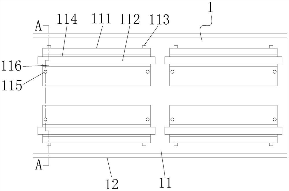
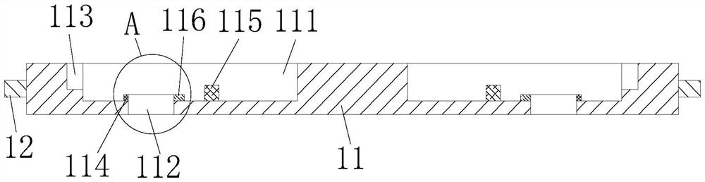
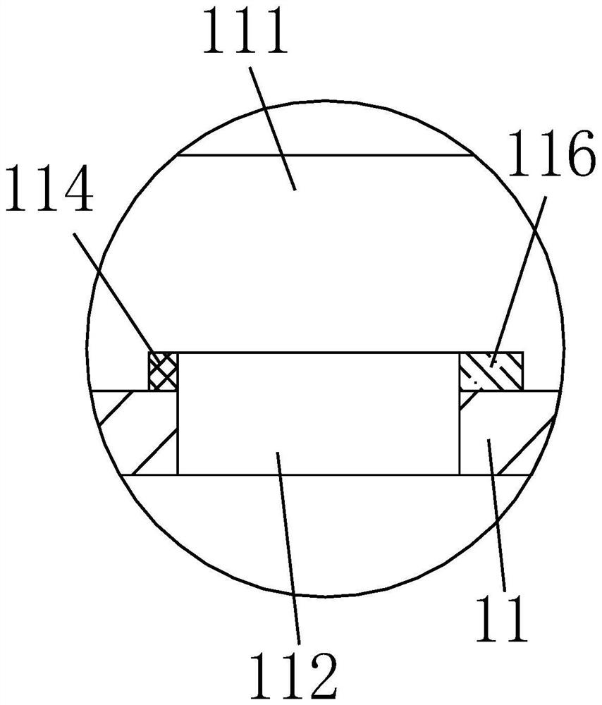
[0052] refer to Figure 1 to Figure 5 , this embodiment discloses a connector bracket, the connector bracket 1 includes a bracket body 11 , and the bracket body 11 is provided with a groove 111 for placing the connector 2 .

[0053] The bottom surface of the groove 111 is provided with a through hole 112, the tinned and degolded part of the pin 22 on the connector 2 can be limited directly above the through hole 112, and the solder can be sprayed to the plug through the through hole 112. Pin 22 is tinned and degolded.

[0054] The first side wall of the groove 112 is provided with a locking groove 113 for locking the positioning rod 23 on the connector 2 .

[0055] A first boss 114 is also provided on the bottom surface of the groove 111, the first boss 114 is between the first side of the groove 111 and the through hole 112, and the upper base of the connector 2 21 can be defined in a space formed between the first boss 114 and the first side of the groove 111 .

[0056] T...

Embodiment 2

[0065] refer to Figure 5 , this embodiment also discloses a connector tinning and gold removal device, including a connector bracket 1, a main box body 3, a flux spraying module 4, a preheating module 5, a gold removal module 6, a tinning module 7 and Central control system 8, the main box body 3 is a hollow structure with the bottom and sides closed and the top open, the opposite ends of the top of the main box body 3 are fixed with slidable connector brackets 1, the main box body 3 is provided with a flux spraying module 4, a preheating module 5, a gold removal module 6 and a tinning module 7 in sequence, and the spraying ends of the flux spraying module 4, the gold removal module 5 and the tinning module 6 are all facing the The opening direction of the top of the main box 3 is set, the connector bracket 1, the flux spraying module 4, the preheating module 5, the gold removal module 6, and the tinning module 7 are all connected to the central control system 8, and through ...


PUM


Abstract

The invention discloses a connector bracket and a connector tinning and degolding device, comprising a bracket body, the bracket body is provided with a groove for placing a connector; the bottom surface of the groove is provided with a through hole, And ensure that the solder can be sprayed to the tinned and degolded part of the pin through the through hole; the side wall of the first side of the groove is provided with a slot for snapping the positioning rod on the connector; A first boss is also arranged on the bottom surface of the groove, and two limit rods are fixed on the bottom surface of the groove, and the limit rods are used to limit the installation position of the protective seat on the connector. The advantage of the present invention is that it can quickly complete the protection process of the non-tinning and gold removal parts of the pins on the connector, cancel the configuration, drying, removal and other processes of the original special protective glue, and improve the tinning and gold removal process of the connector. Efficiency, thereby reducing production cost, and the connector bracket can be reused, further reducing production cost.

Description

technical field [0001] The invention relates to the technical field of connectors, in particular to a connector bracket and a connector tinning and gold removing device. Background technique [0002] With the development of high-density and miniaturized electronic products, the assembly integration between modules is also getting higher and higher. As we all know, multi-row fine-pitch long pin-board connectors are widely used in various electronic modules of aerospace because they can replace traditional complex wire interconnection forms and realize electrical interconnection in a smaller space between multi-level board-level circuits. middle. [0003] For high-reliability electronic products in military, aerospace and other fields, in order to avoid "gold brittleness" and lead to performance degradation of solder joints, it is clearly proposed that gold-plated components need to be tinned and gold-coated before soldering. In Chapter 6.7.2.1 of the QJ3267-2006 standard an...

Claims


Application Information

Patent Timeline
Patent Type & Authority Patents(China)
IPC IPC(8): H01R43/02
CPCH01R43/02H01R43/0235
Inventor 吴瑛陈该青刘颖蒋健乾付任张辉许春停倪靖伟
Owner CHINA ELECTRONIC TECH GRP CORP NO 38 RES INST
Features
  • R&D
  • Intellectual Property
  • Life Sciences
  • Materials
  • Tech Scout
  • Unparalleled Data Quality
  • Higher Quality Content
  • 60% Fewer Hallucinations
Learn More