An improved patch equipment

An improved, patch technology, used in cleaning methods and utensils, printed circuits, chemical instruments and methods, etc., can solve problems such as performance degradation or even failure, and achieve the effect of preventing performance degradation

Active Publication Date: 2021-07-02
深圳市琦轩实创科技有限公司
View PDF4 Cites 0 Cited by
  • Summary
  • Abstract
  • Description
  • Claims
  • Application Information

AI Technical Summary

Problems solved by technology

[0004] In order to solve the technical problems existing in the background technology, the present invention proposes an improved SMT equipment, which can continuously vacuum the electronic components before and during the welding process, and the positioning rod and the spring ensure that the pressure plate can rise while the pressure plate is horizontal, preventing Due to design problems, equipment precision, etc., the distance between the pressure plate and the load-bearing plate is too close to cause the electronic components to be crushed. At the same time, the heat absorbed by the electronic components during the welding process can be transferred out in time to prevent the performance of the electronic components from deteriorating or even failing.

Method used


Image

  • An improved patch equipment
  • An improved patch equipment
  • An improved patch equipment

Examples


Embodiment Construction

[0022] In order to make the object, technical solution and advantages of the present invention clearer, the present invention will be further described in detail below in conjunction with specific embodiments and with reference to the accompanying drawings. It should be understood that these descriptions are exemplary only, and are not intended to limit the scope of the present invention. Also, in the following description, descriptions of well-known structures and techniques are omitted to avoid unnecessarily obscuring the concept of the present invention.

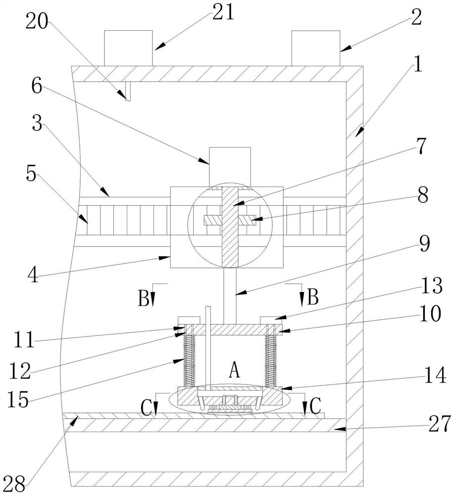
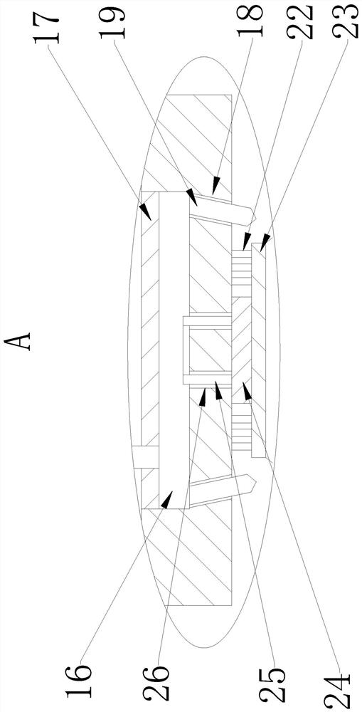
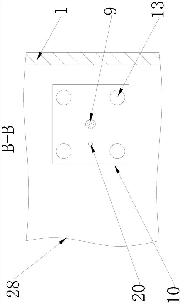
[0023] Such as Figure 1-4 As shown, an improved patch device proposed by the present invention includes a body 1, a box body 4, a rack 5, a power unit 6, a rotating shaft 7, a gear 8, a connecting column 9, a support plate 10, a positioning rod 12, Pressing plate 14, spring 15, patch suction head 22, electronic component 23, heat conduction plate 24, bearing plate 27 and printed circuit board 28;

[0024] The control s...


PUM


Abstract

An improved patch equipment, including a body, a box body, a rack, a power device, a rotating shaft, a gear, a connecting column, a support plate, a positioning rod, a pressure plate, a spring, a patch suction head, electronic components, a heat conducting plate, and a load bearing Board and printed circuit board; slide rails are set in the body; the box body is slidably set on the slide rails; the power device is set on the box body; the bottom of the rotating shaft is rotationally connected with the box body; the gear and the rack are meshed; the rack is set on the slide rails The connecting column is set at the bottom of the box body; the support plate is horizontally set at the bottom of the connecting column; the bottom of the positioning rod is connected with the pressure plate; the spring sleeve is placed on the positioning rod; The bottom; the load-bearing plate is horizontally arranged in the body; the printed circuit board is placed on the load-bearing plate. In the present invention, the dust can be continuously sucked to prevent the dust from affecting the welding, and the pressing plate can be raised horizontally to prevent the electronic components from being crushed, and at the same time, the heat absorbed by the electronic components can be transferred out.

Description

technical field [0001] The invention relates to the technical field of placement equipment, in particular to an improved placement equipment. Background technique [0002] Patch is SMT patch, which refers to surface mount technology. It is a technology that mounts electronic components suitable for SMT production on printed circuit boards, and processes them into circuit boards equipped with electronic components through a certain process. It is a technology that will Surface mount components without leads or short leads are mounted on the surface of printed circuit boards or other substrates, and are soldered and assembled by reflow soldering or dip soldering. When soldering electronic components with many pins, the core of the electronic components will continue to absorb the heat transferred from the pins, which may cause the performance of the electronic components to degrade or even be damaged, and the existing chip placement equipment is prone to false soldering due to...

Claims


Application Information

Patent Timeline
Patent Type & Authority Patents(China)
IPC IPC(8): H05K3/30B08B5/04
CPCB08B5/04H05K3/303
Inventor 严小芳胡明松
Owner 深圳市琦轩实创科技有限公司
Why Eureka
Try Eureka