Adjustable offset moldboard plow

A conventional plow and offset technology, applied in the agricultural field, can solve problems such as easy subsidence, loose loam soil with hard lumps, and reduced flatness of sandy soil, so as to avoid potholes or small holes and improve flatness Effect

Inactive Publication Date: 2020-08-18
姜发威
View PDF0 Cites 0 Cited by
  • Summary
  • Abstract
  • Description
  • Claims
  • Application Information

AI Technical Summary

Problems solved by technology

[0004] The main purpose of the present invention is to overcome the deficiencies of the prior art and provide an adjustable offset plow to solve the problem of soft loamy soil with hard lumps, potholes at the bottom of the groove when cutting soil

Method used


Image

  • Adjustable offset moldboard plow
  • Adjustable offset moldboard plow
  • Adjustable offset moldboard plow

Examples


Embodiment 1

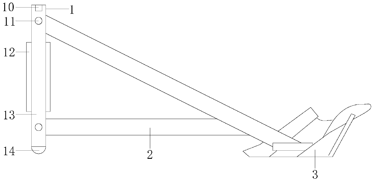
[0026] Example 1 see Figure 1-4 , the present invention provides a technical solution for an adjustable offset conventional plow: its structure includes a mounting plate 1, a frame 2, and a moldboard 3, the mounting plate 1 is locked with the frame 2, and the frame 2 It is installed and connected with the moldboard 3. The installation board 1 is composed of a belt buckle 10, a lock shaft 11, a mounting frame 12, a connection board 13, and a pad wheel 14. The pad wheel 14 is used for the movement of the auxiliary equipment. The wheel 14 has elastic force and can play the effect of buffering. The buckle 10 and the lock shaft 11 are installed on the connecting machine plate 13. The lock shaft 11 is to strengthen the locking of the transmission equipment and the installation machine plate 1. The belt buckle 10 is Strengthen the binding between the transmission equipment and the installation board 1, improve the transmission stability, the installation frame 12 is assembled and co...

Embodiment 2

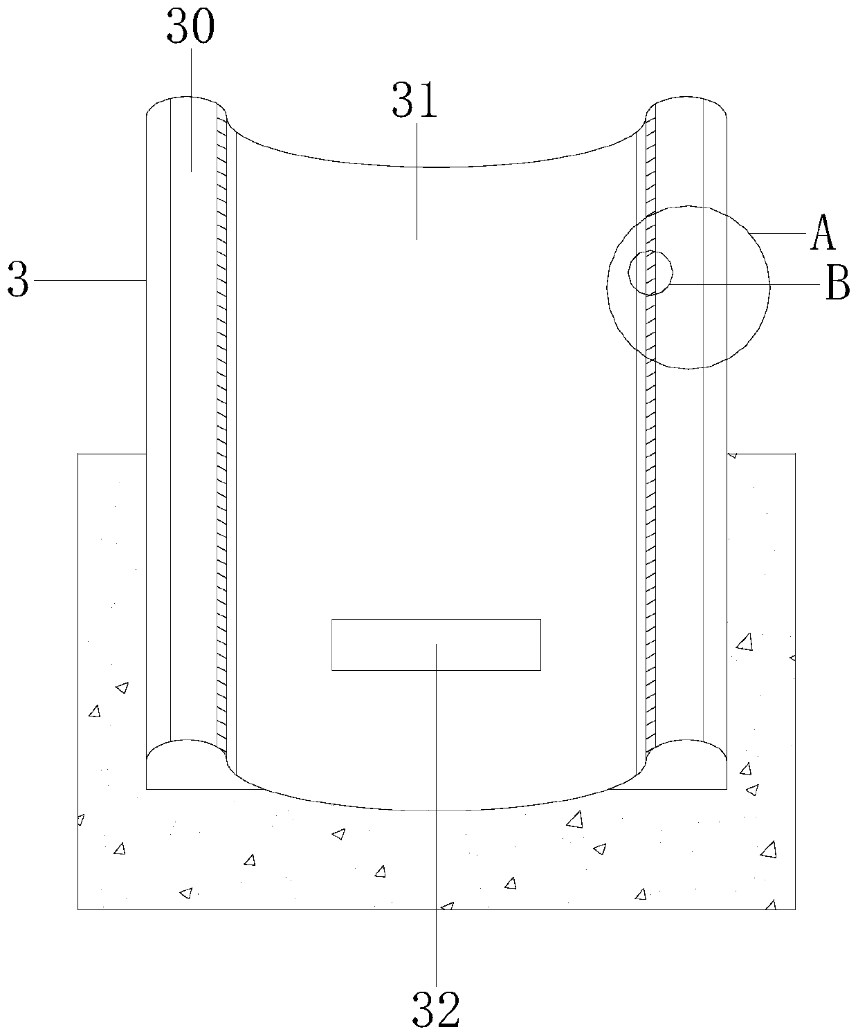
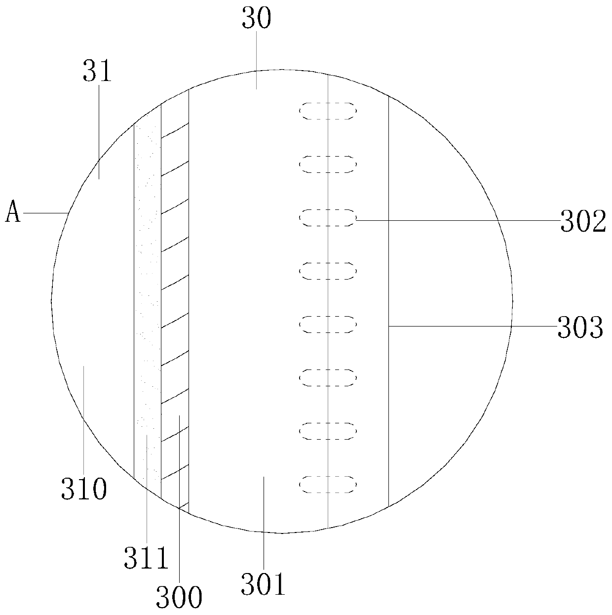
[0028] Example 2 see Figure 5-7 , the present invention provides a technical solution for an adjustable offset plow: the swing shaft structure 32 includes a square pad 320, an auxiliary transmission structure 321, a shaft body 322, and a shaft swing plate 323. The square pad 320 and The shaft swing plate 323 is glued, the auxiliary transmission structure 321 is welded to the shaft swing plate 323, the auxiliary transmission structure 321 is connected to the shaft body 322, and the auxiliary transmission structure 321 includes a latch 3210, a transmission belt 3211, and a spring 3212 , the latch 3210 is embedded and connected with the spring 3212, the latch 3210 is connected with the transmission belt 3211, the latch 3210 is equipped with a bolt rod 400, the movement of the bolt rod 400 controls the tightness of the spring 3212, The elastic force of the spring 3212 changes the swing force of the moldboard 3, reasonably controls the swing distance of the moldboard 3, and reduce...


PUM


Abstract

The invention discloses an adjustable offset moldboard plow. The adjustable offset moldboard plow structurally comprises a mounting machine board, a rack and a moldboard, wherein the mounting machineboard is locked with the rack; the rack is in mounting connection with the moldboard; the mounting machine board consists of a belt fastener, lock shafts, a mounting frame, a connecting machine boardand a pad wheel; the belt fastener and the lock shafts are arranged on the connecting machine board; the mounting frame is in assembling connection with the connecting machine board; the connecting machine board is fastened to the pad wheel; the moldboard comprises wing plates, a shovel board and a swing shaft structure; the wing plates are in mounting connection with the shovel board; the shovelboard is connected with the swing shaft structure via a shaft; each wing plate comprises a bar rail, a wing plate body, a slider structure and a tail plate; each wing plate body is provided with one bar rail; and each slider structure is in mounting connection with the corresponding wing plate body and tail plate. According to the adjustable offset moldboard plow, the shovel board controls a swingamplitude through the swing shaft structure, the moldboard reasonably controls swinging force to avoid formation of a pit or hole while generating driving force to soil, and the swinging force of thewing plate bodies and the conformity of the tail plates and two sides of the soil are controlled through swinging of the wing plates, so that the flatness of two side surfaces of a groove is improved.

Description

technical field [0001] The invention relates to the field of agriculture, in particular to an adjustable offset conventional plow. Background technique [0002] The adjustable offset conventional plow is suitable for dry field cultivation in loamy and sandy loam areas, inserting into the soil (into the soil), cutting out the Shifa (cutting the soil) vertically and horizontally, and breaking and turning it (crushing and turning the soil ), plow out the furrows for sowing and farming. [0003] The loam soil in the prior art is soft with hard lumps. When the soil is cut, the bottom of the ditch is potholed. When the blade is pushed, the moldboard will swing. collapse. Contents of the invention [0004] The main purpose of the present invention is to overcome the deficiencies of the prior art and provide an adjustable offset plow to solve the problem of soft loamy soil with hard lumps, potholes at the bottom of the groove when cutting soil, and occurrence of moldboards when ...

Claims


Application Information

Patent Timeline
IPC IPC(8): A01B15/04A01B15/02A01B71/06
CPCA01B15/02A01B15/04A01B71/06
Inventor 姜发威
Owner 姜发威
Why Eureka
Try Eureka