Tool change method

A cutter body and cutting tool technology, applied to milling cutters, milling machine equipment, grinding machines, etc., can solve the problems of shorter overall length of cutters, discrepancy of milling cutters, reduction of milling cutter specifications, etc., and achieve the effect of improving utilization rate

Active Publication Date: 2020-08-18
孙宝泉
15 Cites 0 Cited by

AI-Extracted Technical Summary

Problems solved by technology

[0003] Taking the milling cutter for processing PCB as an example, the blade of the milling cutter wears out after being used for a period of time. There are two recycling methods in the existing technology. The production method is to cut off the blade part, and then remake the blade on the handle part, but this method ...

Abstract

The invention discloses a tool change method. The tool change method comprises the following steps: S1, establishing XY-axis coordinate information, and obtaining groove position information of a toolto be changed; S2, determining the position of a cutting groove; S3, determining the position of a chip removal groove; and S4, inputting the parameters of the cutting groove and the chip removal groove into a grooving machine tool, and carrying out grinding machining on the cutting groove and the chip removal groove through the grooving machine tool to form a new tool body. According to the method, on the basis of a cutting edge of an old tool, and in the case that the positions of the two grooves are unchanged, a new cutting edge is further machined, so that the utilization rate after toolchange is increased; and the diameter range of the tool change is changed to be 1.9mm and below from the original tool diameter of 2.0mm, however, the diameter range can only be changed to be 1.4mm and below in the existing method.

Application Domain

Milling cuttersGrinding machines

Technology Topic

Manufacturing engineeringMachine tool +1

Image

  • Tool change method
  • Tool change method

Examples

  • Experimental program(1)

Example Embodiment

[0016] The technical solutions in the embodiments of the present invention will be clearly and completely described below in conjunction with the drawings in the embodiments of the present invention.
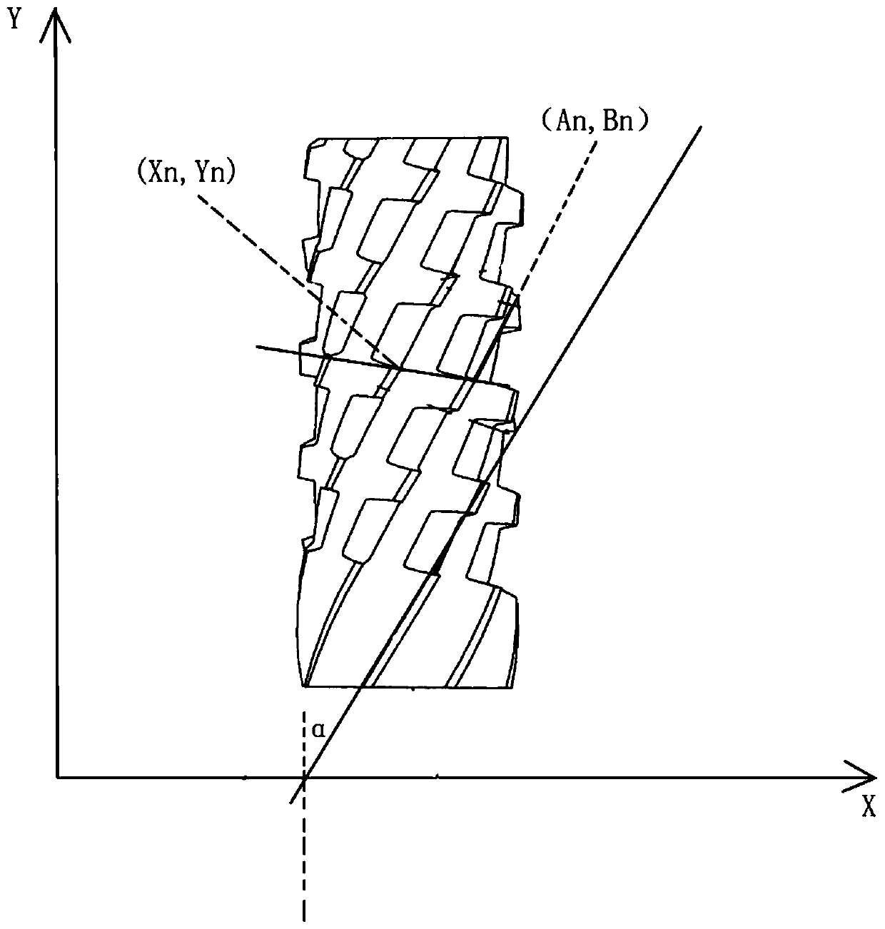
[0017] Such as figure 1 As shown, the present invention proposes a method for modifying a knife, which includes the following steps:
[0018] S1: Establish XY axis coordinate information, and obtain the groove position information of the tool to be changed;
[0019] In this step, it can be obtained by a CCD camera. Specifically, after fixing the recovered old tool on the fixture, rotate the tool to the side with a clearer and complete position. The image information obtained by the CCD camera set on the upper part of the milling cutter is When working, usually only 80% of the length of the milling cutter is used, and the end of the tool holder is not used, so the detection end is an accurate starting position, such as figure 1 As shown, the cutting edge of the cutting groove is recorded and its angle with the Y axis is recorded as α, and the point coordinate information of two adjacent peripheral edges in the spiral direction through the preset chip removal groove is recorded as (Xn, Yn ) And (An,Bn).
[0020] S2: Determine the position of the cutting groove: Determine at least one diagonal line to determine the starting point of the cutting groove through the preset angle information of the end of the plane where the cutting groove is located. By rotating the tool body, when the diagonal line and the cutting groove of the tool body Slot alignment determines the position of the cutting groove;
[0021] S3: Determine the location of the chip removal groove: through the preset chip removal groove along the spiral direction of the point coordinate information of the two adjacent peripheral edges and connect the connection, by rotating the tool body, when the corresponding point reaches the preset point coordinate , It is determined as the path of the chip removal groove to be processed;
[0022] S4: Input the cutting groove including width c, depth h, angle β, and cutting edge number n, and input the information of the chip evacuation groove including width, depth, angle, and cutting edge number to the CNC machine tool, and the cutting groove and chip evacuation groove are processed by the machine tool Milling is performed to form a new cutter body. Among them, machining the tool body and recording parameters are carried out at the same time. When the tool body is rotated, when an edge on the tool body is aligned with the line where the angle is α, the initial position of a cutting groove is determined, and the CNC machine tool is started The tool body is made along the path of the straight line and the process of making the knife is the method in the prior art. For example, the patent publication numbers CN 109158962 A, CN 110712016 A, etc. disclose how to grind the milling cutter, which will not be repeated in this application. Compared with the traditional method of making a knife on a polished rod, this application can determine the initial processing position of the original knife, so that further grinding can be performed on the basis of the old knife, and the old knife can be reformed.
[0023] In addition, it should be noted that: unlike the position determination method of the cutting groove, the chip flute is arranged spirally along the cutter body. If the linear alignment method is used, it is easy to align with the chip flute of the non-identical groove body, resulting in judgment Error, so choose the method of finding points, after confirming the end points of the peripheral edges on both sides of the same chip flute, as the mark point, when the cutter body is rotated, because the connection line of the non-same chip flute is connected with the same chip flute The lines are different, so the line obtained after determining the coordinates is the correct starting position of the chip flute. When the two coordinate points are aligned at the same time, it is determined that the starting point of the chip flute can be determined. Then, when making a tool, The cutter body is rotated, and the groove can not be broken along the determined oblique direction, forming a new chip flute, and then making a new cutter.
[0024] Such as figure 2 As shown in the cross-sectional view of the tool, the solid line is the structure of the new knife. The original tool is 2.0mm in diameter in the broken line, so the maximum diameter of the new knife can be 1.9mm or 1.8mm or 1.7 or 1.6 or 1.5. And so on, and compared to the method of making a new knife after grinding the teeth, the tool in this method can be used 2-3 times more.
[0025] Various modifications to the embodiments will be obvious to those skilled in the art, and the general principles defined herein can be implemented in other embodiments without departing from the spirit or scope of the present invention. Therefore, the present invention will not be limited to the embodiments shown in this document, but should conform to the widest scope consistent with the principles and novel features disclosed in this document.

PUM

no PUM

Description & Claims & Application Information

We can also present the details of the Description, Claims and Application information to help users get a comprehensive understanding of the technical details of the patent, such as background art, summary of invention, brief description of drawings, description of embodiments, and other original content. On the other hand, users can also determine the specific scope of protection of the technology through the list of claims; as well as understand the changes in the life cycle of the technology with the presentation of the patent timeline. Login to view more.

Similar technology patents

Automobile brake control system and control method

ActiveCN103359100Aincrease profitReduce complexity and cost
Owner:GUANGZHOU AUTOMOBILE GROUP CO LTD

Sharing maintenance system ensuring normal operation of wind turbines and realization method thereof

ActiveCN102621971AReduce abnormal downtimeincrease profit
Owner:上海探能实业有限公司

Ultrafine-grinding assisted enzymatic-hydrolysis based preparation method of wheat bran oligosaccharides

InactiveCN104480161Aincrease profitless waste
Owner:TIANJIN UNIVERSITY OF SCIENCE AND TECHNOLOGY

Local discharge development process diagnosis method based on pulse-train analysis

ActiveCN104198898Aincrease profitDeepen understanding
Owner:XI AN JIAOTONG UNIV +2

Intelligent forest fire extinguishing bomb

InactiveCN101703831AEfficient and rapid extinguishmentincrease profit
Owner:HARBIN ENG UNIV

Classification and recommendation of technical efficacy words

  • increase profit

Quantum dot film and backlight module

InactiveCN103487857Aincrease profitImprove light conversion efficiency
Owner:ZHANGJIAGANG KANGDE XIN OPTRONICS MATERIAL

Parking lot booking system and its use method

InactiveCN101101648Aincrease profitReduce use cost
Owner:SHENZHEN TEMOBI SCI &TECH

Hydrodewaxing method for diesel fraction

ActiveCN102453531ARaise the reaction temperatureincrease profit
Owner:CHINA PETROLEUM & CHEM CORP +1

Modified Y molecular sieve

ActiveCN101823726Aincrease profitperformance optimization
Owner:PETROCHINA CO LTD

Full-period electric pressure cooker production control method

InactiveCN107713732ATargetedincrease profit
Owner:GUANGDONG HUILIPU ROAD & BRIDGE INFORMATION ENG
Why Eureka
Try Eureka