Multi-perception sensor, sensor network and perception method applied to Internet of Things

A sensor and Internet of Things technology, applied in the field of sensors, can solve problems such as low efficiency and deviation of perception results, and achieve the effects of expanding the detection and perception range, reducing noise interference, and improving accuracy

Inactive Publication Date: 2020-08-18
魏磊
View PDF8 Cites 2 Cited by
  • Summary
  • Abstract
  • Description
  • Claims
  • Application Information

AI Technical Summary

Problems solved by technology

[0004] The existing sensor networks of the Internet of Things are basically passively sensing environmental changes. At the same time, due to the limitations

Method used


Image

  • Multi-perception sensor, sensor network and perception method applied to Internet of Things
  • Multi-perception sensor, sensor network and perception method applied to Internet of Things
  • Multi-perception sensor, sensor network and perception method applied to Internet of Things

Examples


Embodiment 1

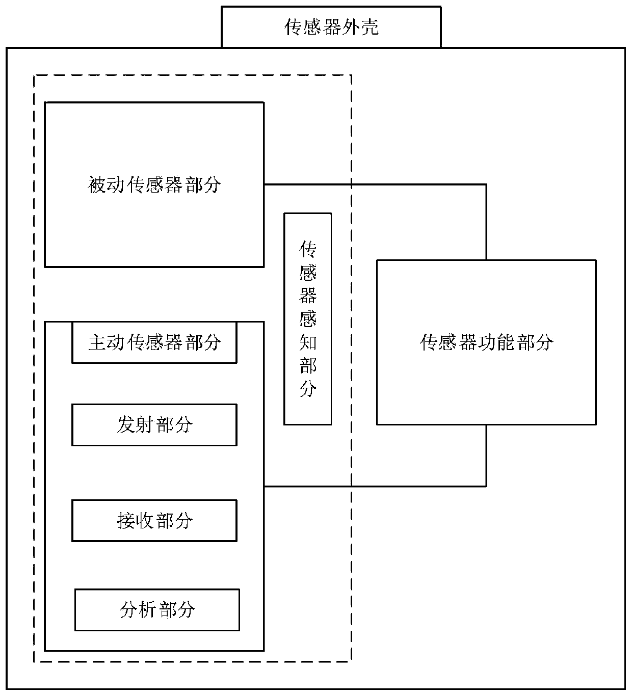
[0025] Such as figure 1 as shown,

[0026] A multi-sensory sensor applied to the Internet of Things, the sensor includes: a sensor housing, a multi-sensory sensor part and a sensor power supply part; the multi-sensory sensor part and the sensor power supply part are all arranged in the sensor housing; the sensor The energy supply part is used to supply energy to the multi-sensory sensor part; the multi-sensory sensor part includes: a passive sensor part and an active sensor part; the passive sensor part passively perceives changes in environmental parameters and obtains the results of parameter changes; the The active sensor part includes: a transmitting part, a receiving part and an analyzing part; the transmitting part comprises a first transmitting part and a second transmitting part, and both the first transmitting part and the second transmitting part emit sound, light and / or electric waves Finally, the receiving part receives the reflected wave and the direct wave; the ...

Embodiment 2

[0029] On the basis of the previous embodiment, the process of performing direct wave filtering by the passive sensor part performs the following steps: use the following formula to calculate the direct wave and the second direct wave of the first transmitting part received by the receiving part through Fourier transform Delay between direct waves of the transmit part: Among them, r 1 (t) is the direct wave of the first transmitting part, F[r 1 (t) is its corresponding Fourier transform; r 2 (t) is the direct wave of the second emission part, F * [r 2 (t)] is the conjugate of its corresponding Fourier transform; f is F[r 1 (t) and F * [r 2 (t)] corresponding frequency, x is the unknown quantity of Fourier transform; Then calculate the cross-correlation coefficient between the direct wave of the first emission part and the direct wave of the second emission part: in, means r 2 (t) inverse Fourier transform; Amplified by 2c times, the reflected wave after fil...

Embodiment 3

[0033] On the basis of the previous embodiment, the functional part of the sensor includes a transformer; the transformer is elastically connected to a magnet through a spring; a metal coil is arranged around the outside of the magnet; The sensor part is connected.


PUM


Abstract

The invention relates to the technical field of sensors, in particular to a multi-perception sensor applied to the Internet of Things, a sensor network and a perception method. The sensor comprises asensor shell, a multi-perception sensor part and a sensor energy supply part, wherein the multi-perception sensor part and the sensor energy supply part are arranged in the sensor shell; the sensor energy supply part is used for supplying energy to the multi-perception sensor part; wherein the multi-perception sensor part comprises a passive sensor part and an active sensor part; the passive sensor part is used for passively sensing the change of environmental parameters and acquiring a parameter change result; the method has the advantages of high sensing efficiency, high sensing accuracy andhigh safety, and has an active sensing function.

Description

technical field [0001] The invention belongs to the technical field of sensors, and in particular relates to a multi-sensing sensor applied to the Internet of Things, a sensor network and a sensing method. Background technique [0002] The Internet of Things (IOT) refers to the real-time collection of any information that needs monitoring, connection, and interaction through various devices and technologies such as information sensors, radio frequency identification technology, global positioning system, infrared sensors, and laser scanners. Objects or processes, collect various required information such as sound, light, heat, electricity, mechanics, chemistry, biology, location, etc., and realize the ubiquitous connection between things and things, things and people through various possible network access , to achieve intelligent perception, identification and management of items and processes. The Internet of Things is an information carrier based on the Internet, traditi...

Claims


Application Information

Patent Timeline
IPC IPC(8): G01D21/02G08C19/30H04B1/10H04L29/08
CPCG01D21/02G08C19/30H04B1/10H04L67/12
Inventor 魏磊仲伟付宋国训刘曌杨秀红
Owner 魏磊
Why Eureka
Try Eureka