Radar measurement device with plane convex lens

A technology of measuring device and plano-convex lens, which is applied in the direction of measuring device, lens, lubricating indicator device, etc., can solve the problems of space layout and occupying a large space, and achieve the effect of simple installation, reduced extension length and saving installation space

Active Publication Date: 2020-08-18
VEGA GRIESHABER GMBH & CO
7 Cites 0 Cited by

AI-Extracted Technical Summary

Problems solved by technology

Due to the desired distance between the radar sensor and the container wall, the arrangement may take up a large amount of s...

Abstract

A radar measurement device for filling level monitoring and/or limit level monitoring includes: a radar signal source (102), which is configured to generate, transmit and/or receive radar signals; anantenna device (104), which is configured to align the radar signal; a plano-convex lens (106), which has a plane particularly facing the filling material, and the plano-convex lens is configured forfocus on the radar signal. The plane (110) of the plano-convex lens (106) is designed as a contact surface (112) so as to be placed on the container (108) during the measurement of the filling level and/or limit level of the filling material in the container (108).

Application Domain

Waveguide hornsMachines/engines +5

Technology Topic

TelecommunicationsRadar signals +3

Image

  • Radar measurement device with plane convex lens
  • Radar measurement device with plane convex lens
  • Radar measurement device with plane convex lens

Examples

  • Experimental program(1)

Example Embodiment

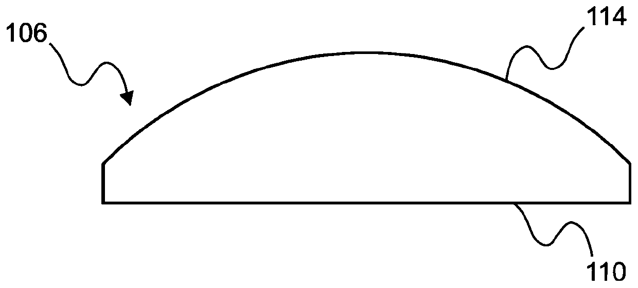
[0034] figure 1 A plano-convex lens 106 according to an exemplary embodiment is shown. The plano-convex lens 106 has a flat surface 110 and a convex surface 114 opposite to the flat surface. In addition, the plane 110 may be fixed on the container 108. The convex surface 114 may be fixed to the antenna device 104.
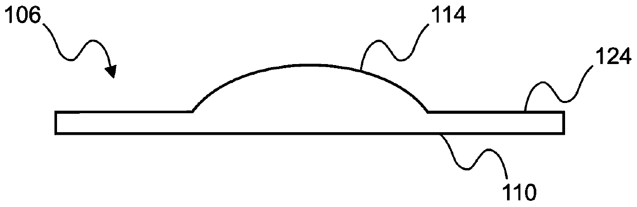
[0035] figure 2 A plano-convex lens 106 according to an exemplary embodiment is shown. The plano-convex lens 106 has a flat surface 110 and a convex surface 114. In addition, the plano-convex lens 106 has a lens shoulder 124 that extends around the convex surface 114. In addition, the lens shoulder 124 may form a surface for fixing the radar measuring device 100 on the container 108.
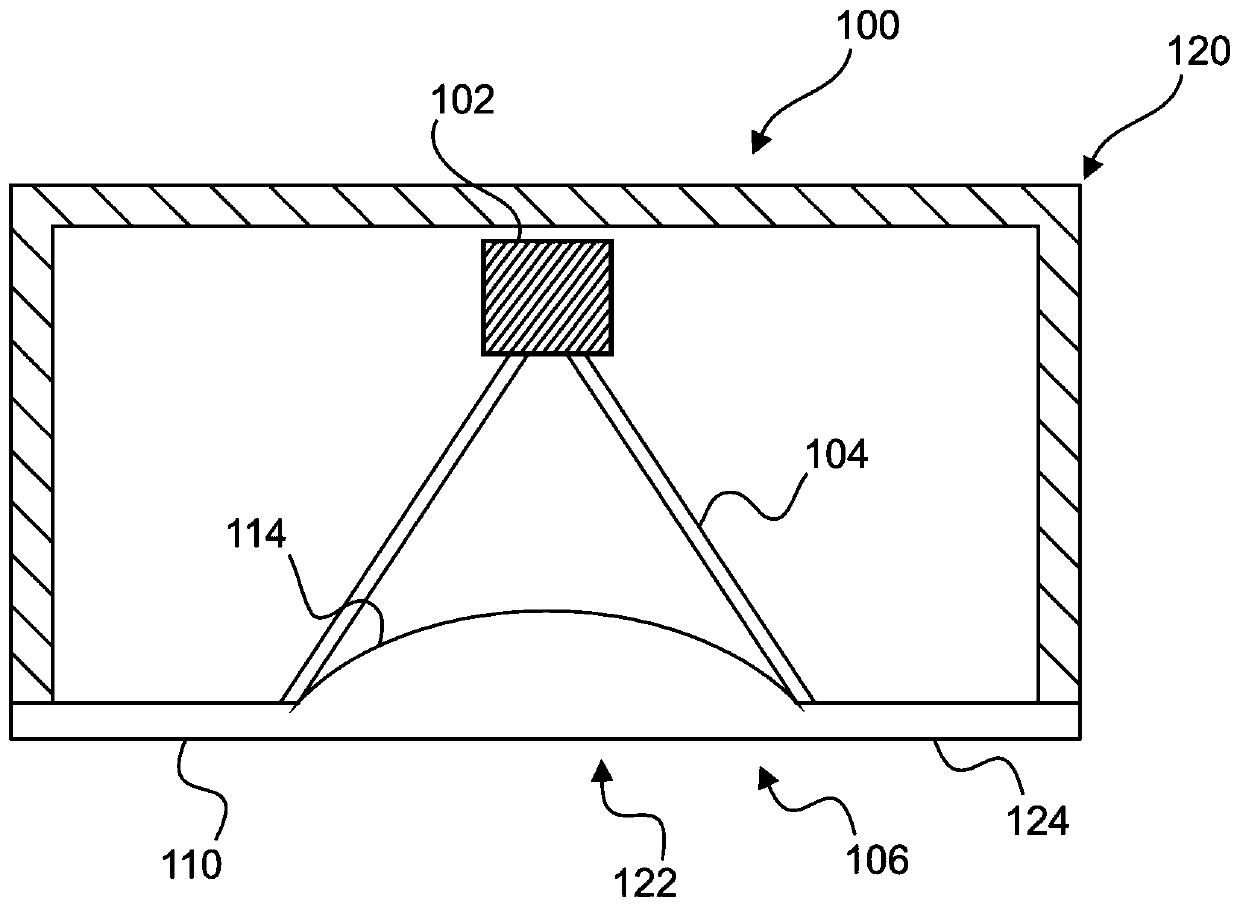
[0036] image 3 A radar measurement device 100 according to an exemplary embodiment is shown. The radar measuring device 100 has a radar signal source 102 on which an antenna device 104 is arranged. The plano-convex lens 106 is arranged on the antenna device 104. The plano-convex lens 106 has a flat surface 110 and a convex surface 114. The convex surface 114 protrudes inward into the antenna device 104. In addition, the radar measurement device 100 has a housing 120. The housing 120 has a bottom surface 122 formed by the flat surface 110 of the plano-convex lens 106. In addition, the plane 110 of the plano-convex lens 106 has a lens shoulder 124, and the lens shoulder 124 also forms a part of the bottom surface 122.
[0037] Figure 4 A radar measurement device 100 according to an exemplary embodiment is shown. The radar measuring device 100 has a radar signal source 102 on which an antenna device 104 is arranged. The plano-convex lens 106 is mounted on the antenna device 104. The plano-convex lens has a convex surface 114 whose diameter is the same as the maximum inner diameter 118 of the antenna device 104. In addition, the radar measuring device 100 is mounted on the container 108, wherein the plano-convex lens 106 is placed on the container 108 flat. In particular, the connection between the plano-convex lens 106 and the container 108 can be established by an adhesive connection.
[0038] Figure 5 A radar measurement assembly 200 is shown, which has a radar measurement device 100 and a container 108 for containing a medium 130. The radar measuring device 100 is arranged on the container 108 through a plano-convex lens 106. The plano-convex lens 106 is a part of the housing 120 of the radar measuring device 100. Furthermore, the radar measurement device 100 has a radar signal source 102 on which an antenna device 104 is arranged. Furthermore, the radar measuring device has an energy storage 126 for supplying energy to the radar measuring device 100, which energy storage 126 is also arranged in the housing 120 of the radar measuring device 100.
[0039] Image 6 A radar measurement device 100 according to an exemplary embodiment is shown. The radar measuring device 100 has a plano-convex lens 106 that is designed to be mounted on a sealing member 128 that is fixed to the antenna device 104. In addition, the radar measurement device 100 has a radar signal source 102. The seal 128 is preferably fixed between the plano-convex lens 106 and the antenna device 104 so that no moisture or contaminants enter the antenna device 104. In addition, the radar measuring device 100 is arranged on the container 108 through a plano-convex lens 106.
[0040] Figure 7 A flowchart illustrating the method steps for installing the radar measuring device 100 according to an exemplary embodiment is shown. Unless otherwise stated, the radar measuring device 100 has Figure 1 to Figure 6 The same components and features of the radar measuring device.
[0041] In step S1, a connection is formed between the plane 110 of the lens of the radar measuring device 100 and the container 108. The connection can be established in particular by adhesive or by a material-bonding connection, a form-locking connection and/or a force-locking connection.
[0042] In addition, it should be pointed out that "comprising" and "having" do not exclude other elements, and the indefinite article "a" or "an" does not exclude a plurality. In addition, it should also be pointed out that the features described with reference to one of the above-mentioned exemplary embodiments can also be applied in combination with other features of other above-mentioned exemplary embodiments. Reference signs in the claims should not be seen as limiting.
[0043] Cross references to related applications
[0044] This application claims the priority of European patent application 19 156 513.4 filed on February 11, 2019, the entire content of which is incorporated herein by reference.

PUM

no PUM

Description & Claims & Application Information

We can also present the details of the Description, Claims and Application information to help users get a comprehensive understanding of the technical details of the patent, such as background art, summary of invention, brief description of drawings, description of embodiments, and other original content. On the other hand, users can also determine the specific scope of protection of the technology through the list of claims; as well as understand the changes in the life cycle of the technology with the presentation of the patent timeline. Login to view more.

Similar technology patents

Novel inclined pin ejecting structure

InactiveCN101347971AReduce extension lengthSimple structure
Owner:MITAC PRECISION TECH(KUNSHAN) CORP

Manual safety device based on driving hammer type emission pistol

ActiveCN105571387ASave installation spaceUse less parts
Owner:CHONGQING JIANSHE IND GRP

Rigid-flexible circuit board

Owner:江苏协和电子股份有限公司

Bottom mold guide rail lifting mechanism

InactiveCN104908304ASave installation spaceSave disassembly time
Owner:JIANGSU NEWAMSTAR PACKAGING MACHINERY

Slipper brake of maglev train

InactiveCN108166339ASave installation spacereduce mechanical wear
Owner:SOUTHWEST JIAOTONG UNIV

Integrated gas path plate of folding structure

ActiveCN105240333Achange volumeSave installation space
Owner:ANHUI SHENGSHI GAOKE TRACK EQUIP

Classification and recommendation of technical efficacy words

  • Reduce extension length
  • Save installation space

Novel inclined pin ejecting structure

InactiveCN101347971AReduce extension lengthSimple structure
Owner:MITAC PRECISION TECH(KUNSHAN) CORP

Silicon slice mark capturing system and method

Owner:SHANGHAI MICRO ELECTRONICS EQUIP (GRP) CO LTD

Air-conditioner internal unit and air conditioner

PendingCN107525154ASave installation spaceCompact installation space
Owner:GREE ELECTRIC APPLIANCES INC OF ZHUHAI

Filter arrangement

InactiveUS20130118964A1save installation space
Owner:IBS FILTRAN KUNST METALLERZEUGNISSE

Multifrequency antenna

InactiveCN1870351ASave installation space
Owner:FOXCONN (KUNSHAN) COMPUTER CONNECTOR CO LTD +1
Why Eureka
Try Eureka