
Through-wall radar imaging method based on wall low-rank sparse constraint

A through-the-wall radar and sparsely constrained technology, applied in radio wave reflection/re-radiation, complex mathematical operations, using re-radiation, etc., can solve the difficulty of obtaining data in empty scenes, without considering wall reflection clutter, imaging quality Issues to be improved to achieve the effect of improving the quality of imaging

Pending Publication Date: 2020-08-18
XI'AN PETROLEUM UNIVERSITY
View PDF3 Cites 6 Cited by
  • Summary
  • Abstract
  • Description
  • Claims
  • Application Information

AI Technical Summary

Problems solved by technology

[0003] In through-wall radar imaging, due to obstacles such as non-transparent walls between the target and the radar antenna, the echo signal received by the antenna contains a large amount of wall reflection clutter, which seriously affects the imaging quality and even makes the target invisible.
In order to facilitate the analysis of the performance of the imaging algorithm, in some traditional imaging algorithms, the wall reflection clutter is not considered or assumed to be filtered out by the background subtraction method before the imaging processing, but in the actual situation, the data of the empty scene Almost hard to obtain, rendering background cancellation unusable
[0004] At present, the existing wall clutter suppression methods and imaging methods are relatively independent processing processes. The echo processing includes two stages of wall clutter suppression and imaging algorithm processing. This processing method has the following two limitations: (1) When the echo signal is under-sampled or defective, the step-by-step processing method is more complicated, and the suppression of clutter is not particularly ideal; (2) This method does not realize the inherent unity of clutter removal and imaging, so imaging quality needs to be improved

Method used


Image

  • Through-wall radar imaging method based on wall low-rank sparse constraint
  • Through-wall radar imaging method based on wall low-rank sparse constraint
  • Through-wall radar imaging method based on wall low-rank sparse constraint

Examples


Embodiment Construction

[0079] The present invention will be described in further detail below in conjunction with the accompanying drawings and specific embodiments, but the embodiments of the present invention are not limited thereto.

[0080] Based on Compressed Sensing (CS), the present invention proposes a through-wall radar imaging algorithm based on low-rank and sparse constraints of walls. The recovery and reconstruction of concealed targets behind walls in the detection environment obtains high-quality target images.

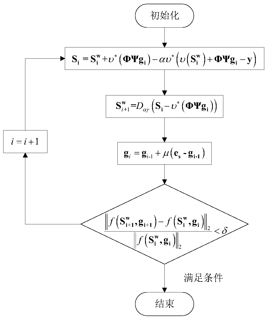
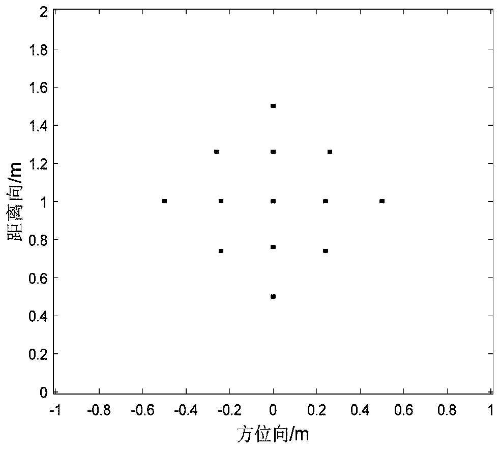
[0081] figure 1 It is the flow chart of the through-wall radar imaging method of the present invention, based on this, to utilize figure 2 The steps for imaging the echo data generated by the target model shown are:

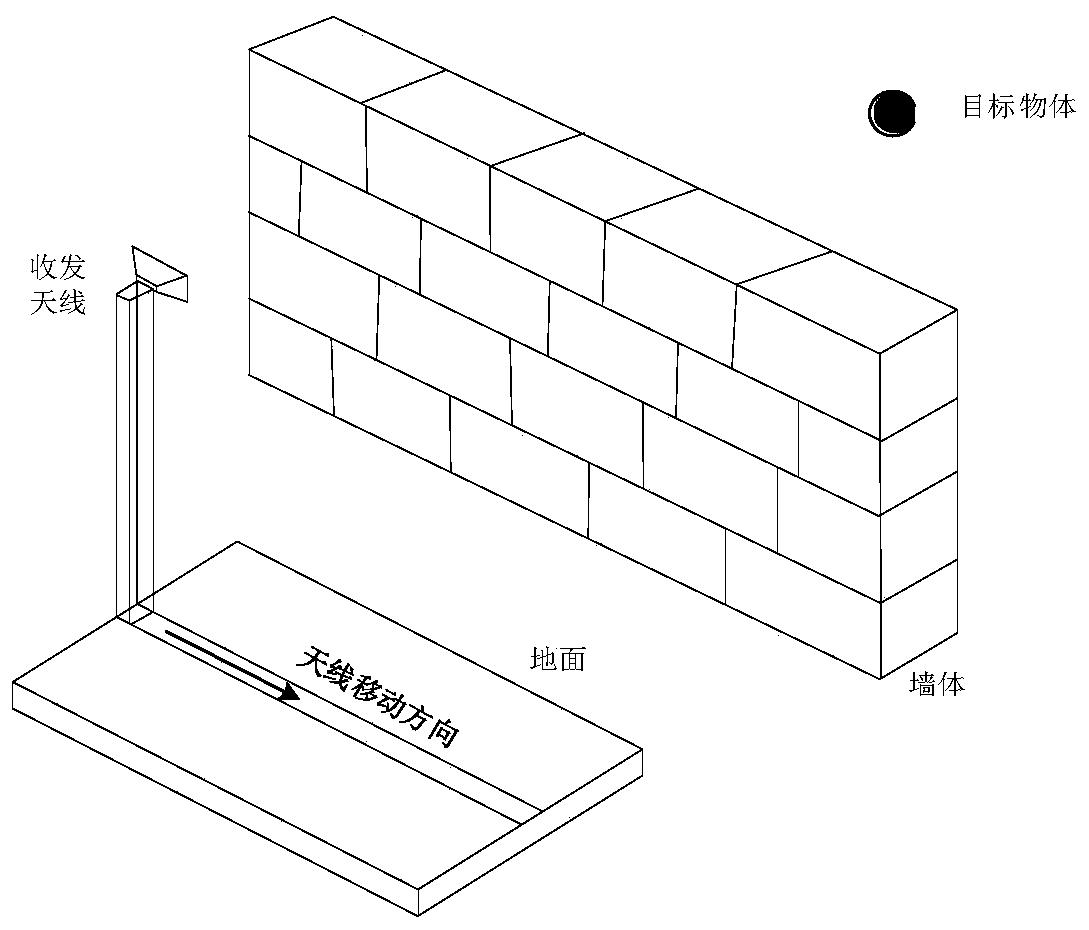
[0082] Step 1: Acquire total echo data. as attached image 3 The imaging geometric model of the through-wall radar is shown, and N measurement positions are set in the moving direction of the radar antenna. The co-located radar transceiver antenna moves at a...


PUM


Abstract

The invention discloses a through-wall radar imaging method based on wall low-rank sparse constraint. Two important characteristics of signals in through-wall radar imaging are utilized; the wall reflects the low rank of clutters and the sparsity of target reflection signals are utilized; according to the invention, a wall clutter suppression and target reconstruction problem is converted into a regularization least square optimization problem; an objective function of the method comprises a data fidelity (least square) item, a nuclear norm regularization item and an l1 norm penalty item, integrated processing of wall clutter suppression and target imaging is achieved, wall clutters are separated out in an iterative loop, meanwhile, target signals are reconstructed and imaged, and the imaging quality is improved.

Description

technical field [0001] The invention belongs to the technical field of microwave imaging, and in particular relates to a through-wall radar imaging method based on low-rank sparse constraints of walls. Background technique [0002] After decades of development, through-the-wall radar has made great progress in terms of theory, technology, systems and products. It transmits electromagnetic wave signals to penetrate non-transparent obstacles such as walls, and processes the received data to realize The detection, positioning, imaging, and identification of hidden targets behind obstacles have important application prospects in civil and military fields such as disaster relief, law enforcement, and anti-terrorism. [0003] In through-wall radar imaging, due to obstacles such as non-transparent walls between the target and the radar antenna, the echo signal received by the antenna contains a large amount of wall reflection clutter, which seriously affects the imaging quality and...

Claims


Application Information

Patent Timeline
IPC IPC(8): G01S13/88G01S13/89G01S7/41G06F17/16G06K9/62
CPCG01S13/888G01S13/89G01S13/006G01S7/418G01S7/414G01S7/411G06F17/16G06F18/28
Inventor 雒明世方阳段沛沛冯建利闫效莺
Owner XI'AN PETROLEUM UNIVERSITY
Learn More