Vehicle cooling apparatus

A technology for cooling devices and vehicles, which is applied in the direction of power devices, liquid cooling, and vehicle components, and can solve problems such as increased compressor power and increased power consumption

Active Publication Date: 2020-08-18
DENSO CORP
View PDF4 Cites 0 Cited by
  • Summary
  • Abstract
  • Description
  • Claims
  • Application Information

AI Technical Summary

Problems solved by technology

On the other hand, when the outdoor heat exchanger operates as a condenser (cooling) like in summer, the power of the compressor for operating the vehicle air conditioner may increase.
As a result, the power consumption of the vehicle may increase

Method used


Image

  • Vehicle cooling apparatus
  • Vehicle cooling apparatus
  • Vehicle cooling apparatus

Examples


no. 1 approach

[0027] Hereinafter, a first embodiment will be described with reference to the drawings. The vehicle cooling device of the present embodiment is applied to an electric vehicle equipped with a rechargeable secondary battery. In addition, the vehicle cooling device performs air-conditioning control in the vehicle interior by a heat pump cycle, and cools a heating element by a cooling cycle.

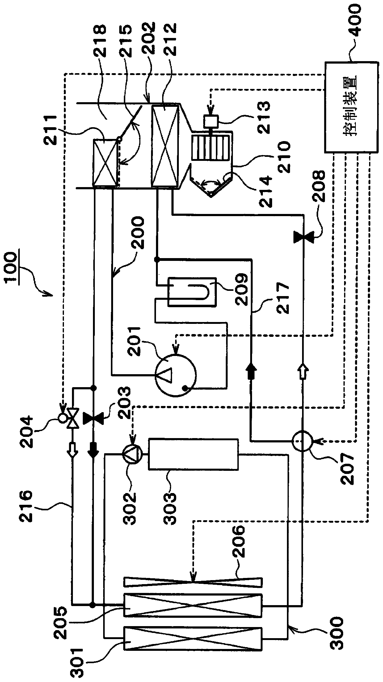
[0028] Such as figure 1 As shown, the vehicle cooling device 100 includes a heat pump cycle 200 , a cooling cycle 300 , and a control device 400 .

[0029] The heat pump cycle 200 is a refrigeration cycle that heats or cools the vehicle interior supply air that is blown into the vehicle interior, which is a space to be air-conditioned. The heat pump cycle 200 performs a heating operation and a cooling operation by switching the refrigerant flow path. The operation in which the air supplied to the vehicle interior is cooled to cool the interior of the vehicle.

[0030] Specifically, the ...

no. 2 approach

[0081] In this embodiment, differences from the first embodiment will be described. Such as Figure 5 As shown, the cooling cycle 300 includes a first cooling cycle 304 and a second cooling cycle 305 . In addition, in Figure 5 Devices other than the outdoor heat exchanger 205 in the heat pump cycle 200 are omitted here. In addition, the control device 400 is omitted.

[0082] The first cooling cycle 304 is a circuit for circulating cooling water through the first flow path 306 and the second flow path 307 . The first flow path 306 and the second flow path 307 are connected by a first connection part 308 and a second connection part 309 .

[0083] The first flow path 306 has a first radiator 310 and a first supply machine 311 . The first supply machine 311 makes cooling water flow from the first connection part 308 to the second connection part 309 through the first radiator 310 . The first feeder 311 is controlled by the control device 400 .

[0084] The second flow pa...

no. 3 approach

[0103] In this embodiment, differences from the second embodiment will be described. Such as Figure 8 As shown, the first cooling cycle 304 has a detour flow path 330 and a solenoid valve 331 .

[0104] The detour channel 330 is provided in parallel with the first radiator 310 and bypasses the first radiator 310 . That is, the detour flow path 330 is a flow path connecting the inflow side of the first radiator 310 and the inflow side of the first supply machine 311 .

[0105] The solenoid valve 331 is provided in the bypass flow path 330 . The solenoid valve 331 is controlled by the control device 400 to adjust the flow rate of the cooling water flowing to the bypass flow path 330 .

[0106]In the cooling cycle 300 described above, when the outdoor heat exchanger 205 is made to function as a condenser according to the air conditioner request, the control device 400 obtains the temperature of the cooling water, and repeatedly executes the preheating mode and the cooling mod...


PUM


Abstract

This vehicle cooling apparatus comprises an outdoor heat exchanger (205), a radiator (301, 310, 319), an air blower (206), and a control device (400). In the outdoor heat exchanger, a refrigerant in arefrigeration cycle flows by a compressor (201) of a vehicle. The radiator has a heat transport medium flowing therethrough by a feeder (302, 311, 322) of the vehicle, and is disposed closer to the vehicle front side than is the outdoor heat exchanger. The air blower is disposed closer to the vehicle rear side than is the outdoor heat exchanger. The control device controls the compressor and thefeeder according to an air-conditioning request of the vehicle. The air blower includes: a forward rotation mode in which air is blown from the radiator side to the outdoor heat exchanger side; and areverse rotation mode in which air is blown from the outdoor heat exchanger side to the radiator side. When causing the outdoor heat exchanger to function as a condenser according to the air-conditioning request, the control device causes the blower to operate in the reverse rotation mode.

Description

[0001] Cross-reference of related applications [0002] This application is based on Japanese Patent Application No. 2018-000907 filed on January 8, 2018, the contents of which are cited here. technical field [0003] The present invention relates to a vehicle cooling device. Background technique [0004] Conventionally, for example, Patent Document 1 proposes a cooling device for a vehicle mounted on a vehicle. The vehicle cooling device has a structure in which the low-water temperature radiator is arranged on the front side of the vehicle relative to the outdoor heat exchanger. [0005] prior art literature [0006] patent documents [0007] Patent Document 1: Japanese Patent Laid-Open No. 2013-126858 [0008] In the above technique, the temperature of the inlet air of the outdoor heat exchanger rises due to the influence of the heat radiation amount of the low water temperature radiator. Therefore, when the outdoor heat exchanger operates as an evaporator (heating) ...

Claims


Application Information

Patent Timeline
IPC IPC(8): B60H1/22B60H1/32B60K11/04F01P3/18F01P3/22F01P7/04
CPCB60K11/085B60K11/02Y02T10/88B60H1/00921B60H1/00828
Inventor 西冈侑作川口雄史
Owner DENSO CORP
Why Eureka
Try Eureka