Failure sensing device, monitoring and control system, and failure sensing method

A fault detection and fault technology, applied in the field of fault detection devices, can solve problems such as abnormal operation, and achieve the effect of reducing the burden

Pending Publication Date: 2020-08-18
MITSUBISHI ELECTRIC CORP
View PDF9 Cites 1 Cited by
  • Summary
  • Abstract
  • Description
  • Claims
  • Application Information

AI Technical Summary

Problems solved by technology

The above-mentioned monitoring and control system sometimes does not operate normally due to long-term operation and simultaneous operation of multiple users.

Method used


Image

  • Failure sensing device, monitoring and control system, and failure sensing method
  • Failure sensing device, monitoring and control system, and failure sensing method
  • Failure sensing device, monitoring and control system, and failure sensing method

Examples


Embodiment approach 1

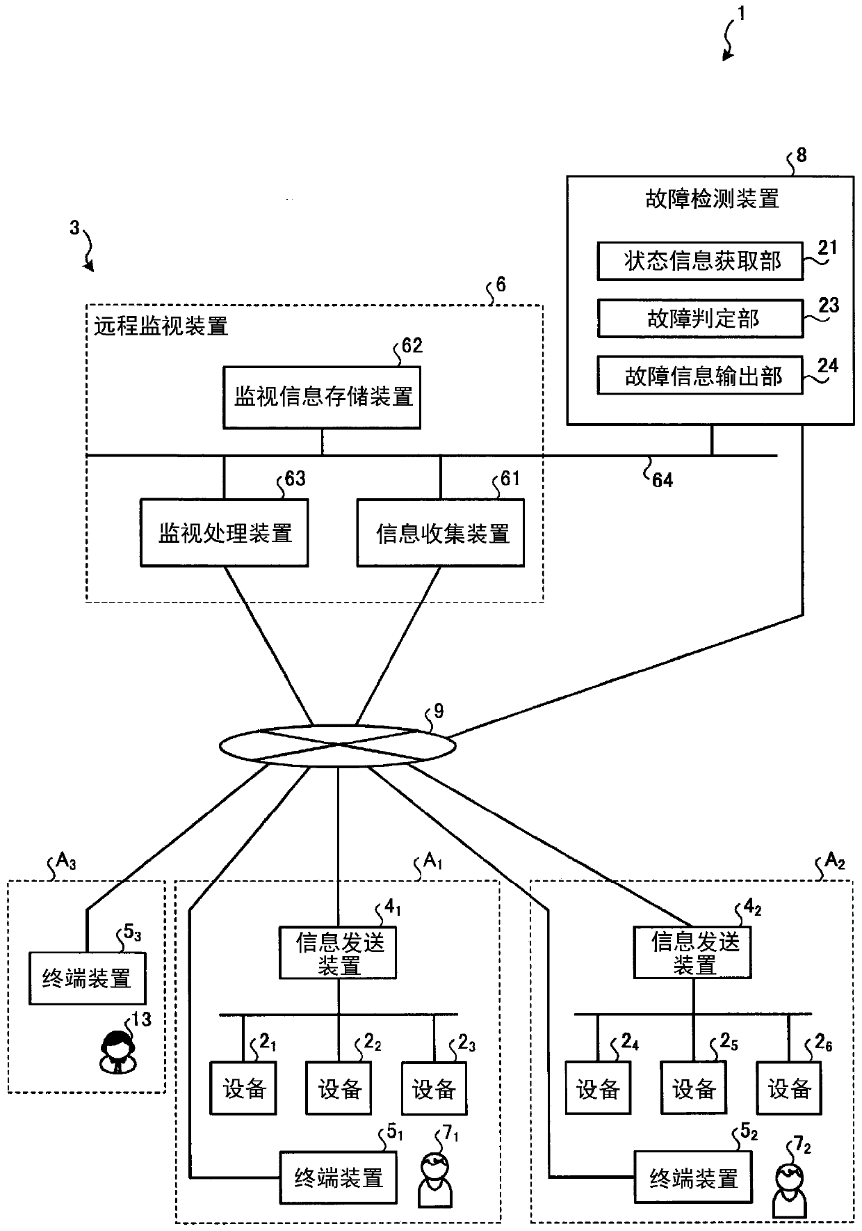
[0036] figure 1 It is a figure which shows the structural example of the monitoring control system concerning Embodiment 1. figure 1 The monitoring and control system 1 shown performs equipment 2 1 ~2 6 monitoring of the status of the device as well as 2 1 ~2 6 control. device 2 1 ~2 6 For example, equipment installed in plants or public facilities such as water purification plants, power plants, and factories includes one or more devices. device 2 1 ~2 3 Set up in the 1st area A 1 , device 2 4 ~2 6 Set up in the 2nd area A 2 . Below, in the wrong device 2 1 ~2 6 Each of the cases is separately distinguished, referred to as device 2.

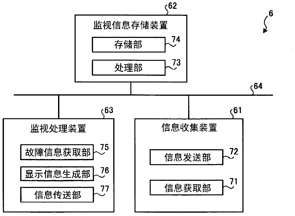
[0037] The monitoring and control system 1 includes a remote monitoring system 3 that monitors equipment 2 installed in a remote place, and a failure detection device 8 that detects a failure of the remote monitoring system 3 . In addition, although not shown in figure, the monitoring control system 1 includes the equipment cont...

Embodiment approach 2

[0148] Embodiment 2 differs from Embodiment 1 in that processing for estimating the details of the failure is added. Hereinafter, the same code|symbol is attached|subjected to the structural element which has the same function as Embodiment 1, and description is abbreviate|omitted, and it demonstrates centering on the point which differs from the failure detection apparatus 8 of Embodiment 1. FIG.

[0149] Figure 19 It is a figure which shows the structural example of the failure detection apparatus concerning Embodiment 2. Such as Figure 19 As shown, the fault detection device 8A according to Embodiment 2 differs from the fault detection device 8 in that a processing unit 20A is provided instead of the processing unit 20 of the fault detection device 8 . The processing unit 20A differs from the processing unit 20 in that it includes a failure determination unit 23A instead of the failure determination unit 23 .

[0150] The failure determination unit 23A further includes a...


PUM


Abstract

Provided is a failure sensing device (8) comprising a state information acquisition part (21), a failure assessment part (23), and a failure information output part (24). The state information acquisition part (21) acquires, from a remote monitoring system (3) for monitoring remotely disposed facilities (21-26), state information indicating the state of the remote monitoring system (3). On the basis of the state information acquired by the state information acquisition part (21), the failure assessment part (23) assesses a failure of the remote monitoring system (3), and generates failure information indicating details of the assessed failure. The failure information output part (24) outputs the failure information generated by the failure assessment part (23).

Description

technical field [0001] The invention relates to a fault detection device, a monitoring control system and a fault detection method. Background technique [0002] Conventionally, there are known monitoring and control systems that monitor and control equipment such as factories and public facilities. The monitoring and control system described above may not operate normally due to long-time operation, simultaneous operation by a plurality of users, and the like. When the supervisory control system does not operate normally, the system administrator confirms the contents of the system failure by checking the status of each device constituting the supervisory control system and the operation history of the user. [0003] Patent Document 1 proposes a computer system that stores user operation history when a system failure occurs, and issues a warning if the current operation is included in the operation history that caused the failure, so as to avoid system failure. [0004] p...

Claims


Application Information

Patent Timeline
Patent Type & Authority Applications(China)
IPC IPC(8): G06F11/07H04Q9/00
CPCH04Q9/00G06F11/07G06F11/0709G06F11/0736G06F11/0751G06F11/079G06F11/0775G06F11/0787G01M99/00G05B23/0275
Inventor 柳原慎太郎
Owner MITSUBISHI ELECTRIC CORP
Why Eureka
Try Eureka