Rail clamping device and automatic force increasing rail clamping system
A rail clamp and track technology, applied in the direction of traveling mechanism, load hanging components, transportation and packaging, etc., can solve the problems of complex structure of windproof device and general windproof effect, so as to ensure the ability of windproof and anti-skid, without manual labor, The effect of reducing labor costs
- Summary
- Abstract
- Description
- Claims
- Application Information
AI Technical Summary
Problems solved by technology
Method used
Image


Examples
Embodiment 1
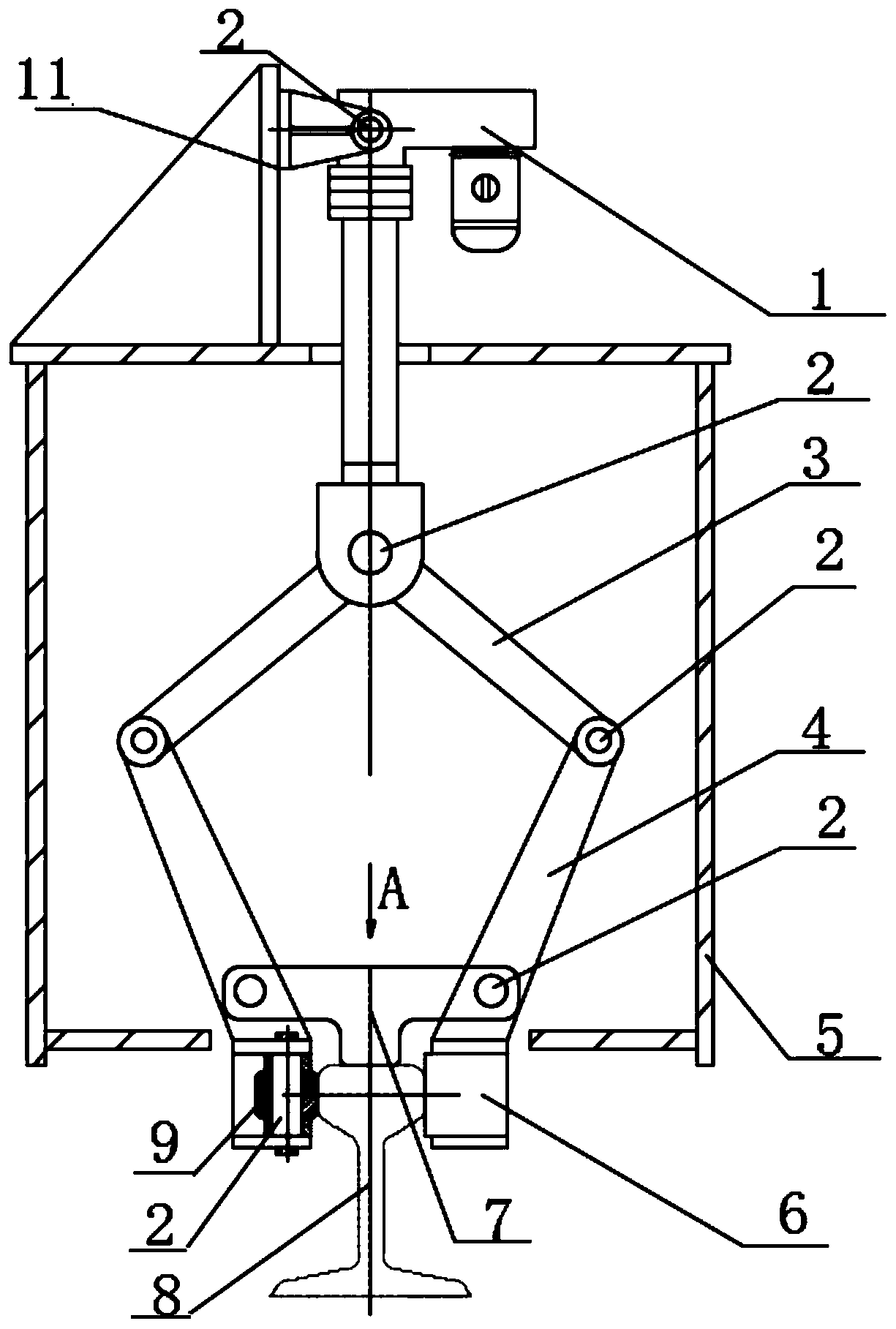
[0033] like figure 1 and figure 2As shown, a rail clamp includes a clamping part I and a clamping part II, the clamping part I clamps one side of the rail 8, the clamping part II clamps the other side of the rail 8, the clamping part I and the clamping part II The clamping parts II are respectively connected to the driving device 1 through the pincer arms 4, the clamping surface I9 in the clamping part I is in contact with one side of the track 8, the middle part of the clamping surface I9 is attached to the side of the track 8, and the clamping surface I9 There are gaps between the two ends of the two sides and the side of the track 8, so that the clamping surface I9 can rotate when the wind force becomes stronger and produce a tendency to expand outward relative to the track 8; the clamping surface II6 in the clamping part II and the track 8 The other side is in contact, and the clamping surface II6 is completely attached to the other side of the track 8. When the clampi...
Embodiment 2
[0038] Basically the same as embodiment 1, preferably, the clamping surface II6 and the clamping surface I9 are provided with a proximity switch, when the clamping surface II6 and the clamping surface I9 are in contact with the track 8 and clamped, the proximity switch generates a signal to the main The controller and the main controller are set in the control room. The operator can know that the clamping surface II6 and the clamping surface I9 are respectively clamped with the track 8 by observing the main controller. When the clamping part has been clamped with the track 8, the driving device 1 still continues to work, causing unnecessary power output, saving energy consumption, and improving the timeliness of the whole process; more specifically, the clamping surface I9 and the clamping surface II6 are provided with The pattern increases the friction between the clamping surface I9 and the clamping surface II6 and the track 8 respectively, so that relative sliding between th...
Embodiment 3
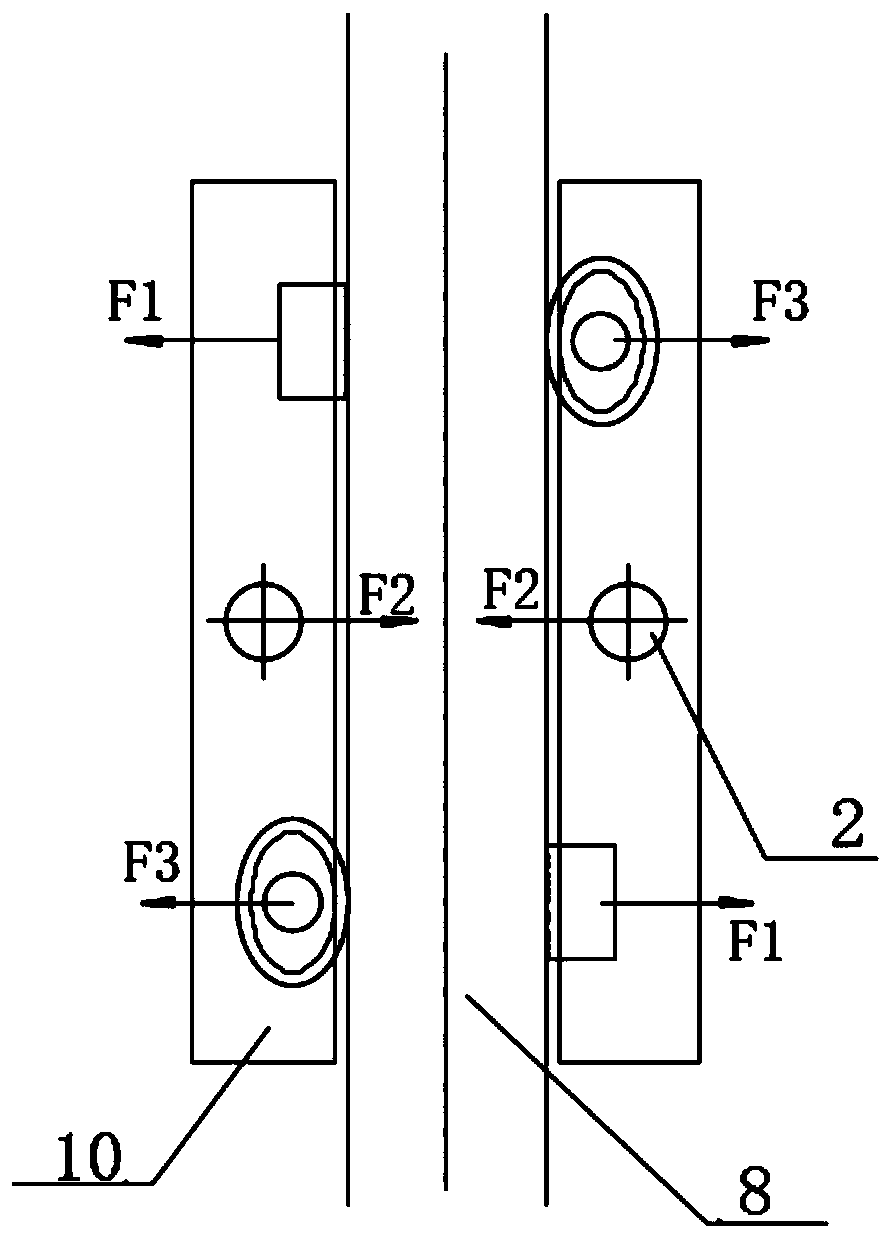
[0040] An automatic booster rail clamping system, including at least two rail clamps as described in any one of the above-mentioned embodiments 1-2, the clamping part I and the clamping part II in the rail clamping device are respectively arranged on the track 8, the clamping part I and the clamping part II in two adjacent rail clamps are arranged alternately on one side of the track 8, specifically referring to the adjacent rail clamps and the track on the same side of the track 8 8. The clamping part of the contact is inconsistent, so as to figure 2 For example, the left side of track 8 is the clamping surface I9 in one rail clamp and the clamping surface II 6 in another rail clamp, and the right side of track 8 is the clamping surface in one rail clamp respectively II 6 and the clamping surface I9 in another rail clamp; in this implementation, the number of the rail clamp is two.
[0041] The reason why the present invention staggers the clamping part I and the clamping p...
PUM
 Abstract
Description
Claims
Application Information
 - R&D
- Intellectual Property
- Life Sciences
- Materials
- Tech Scout
- Unparalleled Data Quality
- Higher Quality Content
- 60% Fewer Hallucinations
Browse by: Latest US Patents, China's latest patents, Technical Efficacy Thesaurus, Application Domain, Technology Topic, Popular Technical Reports.
© 2025 PatSnap. All rights reserved.Legal|Privacy policy|Modern Slavery Act Transparency Statement|Sitemap|About US| Contact US: help@patsnap.com