
Road surface rainwater side drainage and permeation structure and construction method

A construction method and rainwater technology are applied to the road surface rainwater side drainage infiltration structure, and the construction field of constructing the above-mentioned pavement rainwater side drainage infiltration structure can solve the problems of water damage to green belts and roadbeds, affecting road driving safety, etc., and improve the service life. , Improve the utilization rate and reduce the effect of scour force

Pending Publication Date: 2020-08-21
湖南省第三工程有限公司
View PDF0 Cites 2 Cited by
  • Summary
  • Abstract
  • Description
  • Claims
  • Application Information

AI Technical Summary

Problems solved by technology

[0003] The present invention provides a construction method for the rainwater side drainage infiltration structure on the pavement, so as to solve the phenomenon of water damage to the green belt and the roadbed at the rainwater collection mouth caused by setting the rainwater collection mouth on the curb in the prior art, and the influence Technical Problems of Road Driving Safety

Method used


Image

  • Road surface rainwater side drainage and permeation structure and construction method
  • Road surface rainwater side drainage and permeation structure and construction method
  • Road surface rainwater side drainage and permeation structure and construction method

Examples


Embodiment Construction

[0028] The embodiments of the present invention will be described in detail below with reference to the accompanying drawings, but the present invention can be implemented in various ways defined and covered below.

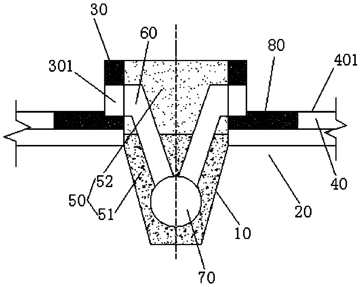
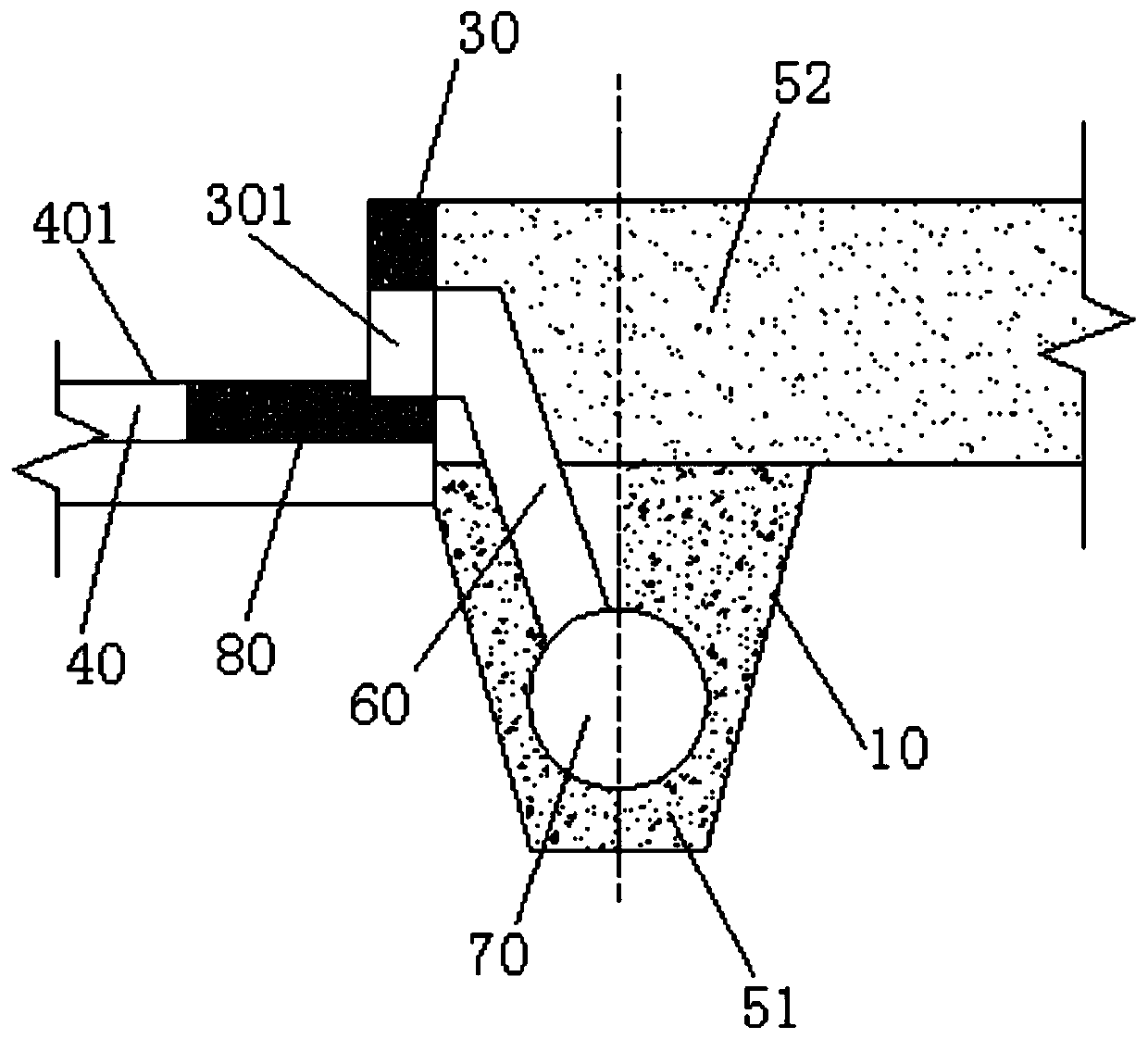
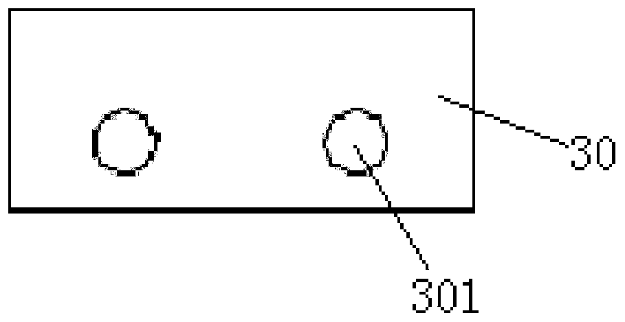
[0029] refer to figure 1 and figure 2 , the preferred embodiment of the present invention provides a pavement rainwater side drainage infiltration structure, comprising: a seepage ditch 10 formed by indentation of the roadbed base surface, the seepage ditch 10 extends along the length direction of the roadbed 20, and the seepage ditch 10 is at least On one side of the subgrade surface, a curb curb 30 is vertically supported, and the curb curb 30 extends along the length direction of the subgrade 20, and the space formed by the seepage ditch 10 and the curb curb 30 is filled with water for infiltration. A percolation layer 50 for filtering rainwater. A plurality of drainage through holes 301 are provided on the curb side stone 30, and the plurality of drainage t...


PUM


Abstract

The invention discloses a road surface rainwater side drainage and permeation structure and a construction method. The structure comprises a percolation ditch formed by recessing a roadbed basal plane, wherein curb curbstone is vertically arranged on the roadbed basal plane on at least one side of the percolation ditch in a supporting mode, the curb curbstone extends in the length direction of theroadbed, and a space formed by the percolation ditch and the curb curbstone is filled with a percolation layer used for percolating rainwater. A plurality of drainage through holes are formed in thecurb curbstone, the drainage through holes are sequentially distributed in the length direction of the curb curbstone at intervals, the water inlet end of each drainage through hole is communicated with the road surface of a road layer laid on the roadbed basal plane, and the drainage ends of the drainage through holes are communicated with the percolation layer so as to enable rainwater on the road surface to seep into the percolation layer. According to the road surface rainwater side drainage and permeation structure, when rainwater is drained through the plurality of drainage through holes, the drainage rate can be increased, the scouring force of drainage on the roadbed and a green belt soil body is reduced at the same time, and scouring water damage to the roadbed and the green beltdue to too large rainfall is avoided.

Description

technical field [0001] The invention relates to the field of side drainage of road surface rainwater, in particular to a permeable structure for side drainage of road surface rainwater. In addition, the present invention also relates to a construction method for constructing the above-mentioned rainwater side drainage permeable structure on the pavement. Background technique [0002] At present, the country vigorously advocates the construction of sponge cities. During the construction of the Buban Connecting Road Project in Longgang District, Shenzhen, which is undertaken by our company, the road is set on the road curbs to infiltrate rainwater into the subgrade soil according to the requirements of the sponge city construction in Shenzhen. The water inlet (rainwater collection port) of the body and the green belt soil. However, due to the long construction time span of the project, during the construction process, it was found that the water flow at the inlet of the rainw...

Claims


Application Information

Patent Timeline
Patent Type & Authority Applications(China)
IPC IPC(8): E01C11/22E03F5/046E03F3/02E03F3/06
CPCE01C11/223E01C11/227E03F5/046E03F3/02E03F3/06
Inventor 向宗幸戴习东孙志勇吴凯明李至王俊杰刘毅李龙
Owner 湖南省第三工程有限公司
Learn More