A Spatial Light Adaptive Coupling Device Based on Crystal Electro-optic Effect

An electro-optical effect and coupling device technology, applied in the field of optoelectronic communication, can solve the problems of low coupling efficiency, difficult structure optimization, low spatial optical coupling efficiency, etc., and achieve the effects of increasing numerical aperture, device structure optimization, and high application value.

Active Publication Date: 2021-11-09
天津寰宇星通科技有限公司
View PDF4 Cites 0 Cited by
  • Summary
  • Abstract
  • Description
  • Claims
  • Application Information

AI Technical Summary

Problems solved by technology

[0005] In order to solve the problems of low spatial optical coupling efficiency, complex structure, and difficult adjustment, the present invention provides a non-mechanized electronically controlled dynamic adjustable spatial optical high-efficiency automatic coupling device based on crystal electro-optic effect
Compared with the traditional coupling system, it solves the problems of difficult structure optimization, high processing difficulty and low coupling efficiency

Method used


Image

  • A Spatial Light Adaptive Coupling Device Based on Crystal Electro-optic Effect
  • A Spatial Light Adaptive Coupling Device Based on Crystal Electro-optic Effect
  • A Spatial Light Adaptive Coupling Device Based on Crystal Electro-optic Effect

Examples


Embodiment Construction

[0020] In order to explain in detail the technical content, structural features, achieved goals and effects of the technical solution, the following will be described in detail in conjunction with specific embodiments and accompanying drawings.

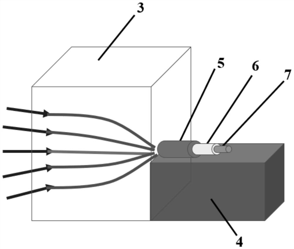
[0021] The present invention proposes a spatial light adaptive coupling device based on the crystal electro-optical effect, which includes a self-focusing lens, a support platform and a trapezoidal optical fiber. The trapezoidal optical fiber includes a multimode optical fiber and a single-mode optical fiber. At the focal point of the lens, the trapezoidal optical fiber is arranged on the supporting platform.

[0022] A preferred embodiment of the present invention is a spatial light adaptive coupling device based on crystal electro-optic effect, please refer to figure 1 As shown, it is a schematic structural diagram of a spatial light adaptive coupling device based on the crystal electro-optical effect, and the device includes a self...


PUM

PropertyMeasurementUnit
diameteraaaaaaaaaa
diameteraaaaaaaaaa
diameteraaaaaaaaaa

Abstract

The invention belongs to the technical field of optoelectronic communication, and more particularly relates to a space light adaptive coupling device based on crystal electro-optic effect. It includes a self-focusing lens, a support platform and a trapezoidal optical fiber. The core diameter of the trapezoidal optical fiber decreases from the front section to the tail section. The trapezoidal optical fiber includes at least three sections of optical fiber, wherein the front section is a multimode fiber, and the tail section is a single-mode fiber. The front end of the optical fiber is located at the focal point of the self-focusing lens, and the trapezoidal optical fiber is arranged on a supporting platform. The device has the characteristics of automatic response and dynamic adjustment, and can adjust the potential distribution according to the coupling efficiency, thereby changing the focusing constant and focal length of the self-focusing lens, realizing the optimization of the device structure, and ensuring efficient coupling of space light to single-mode fiber. In addition, because the device is easy to control, has no mechanical structure and has a high degree of integration, the device has higher application value.

Description

technical field [0001] The invention belongs to the technical field of optoelectronic communication, and more particularly relates to a space light adaptive coupling device based on crystal electro-optic effect. Background technique [0002] The electro-optic effect of a crystal refers to an effect in which the optical refractive index of a crystal changes due to an external electric field. When the refractive index varies linearly with an applied electric field, the effect is called the linear electro-optic effect. For LiNbO 3 For crystals, when the direction of the applied electric field is along the Z direction of the crystal optical axis, the direction of the main axis does not change and the refractive index in each direction is related to the strength of the applied electric field. [0003] A self-focusing lens means that the refractive index of the medium gradually changes along the radial direction according to a certain rule, and the refractive index distribution ...

Claims


Application Information

Patent Timeline
Patent Type & Authority Patents(China)
IPC IPC(8): G02F1/03G02B6/32
CPCG02B6/32G02F1/0311
Inventor 刘波蔡岳丰刘海锋林炜张昊
Owner 天津寰宇星通科技有限公司
Why Eureka
Try Eureka