Nuclear power plant spent fuel vertical storage dry shaft and spent fuel storage tank stacking and recycling method

A technology for spent fuel and nuclear power plants, applied in the field of nuclear power, can solve problems such as insufficient reprocessing capacity, poor economy, and large storage area, and achieve the effects of overcoming insufficient reprocessing capacity, good seismic stability, and protecting structural safety

Pending Publication Date: 2020-08-21
中广核工程有限公司 +3
View PDF3 Cites 1 Cited by
  • Summary
  • Abstract
  • Description
  • Claims
  • Application Information

AI Technical Summary

Problems solved by technology

[0003] However, the concrete silo with the above structure has the following problems: 1) The unit storage capacity of the existing concrete silo is small, and the economy is poor: the existing single concrete silo can only accommodate one spent fuel storage tank, and a single spent fuel storage tank The body thickness is small, only 12mm ~ 14mm, and the weight of a single storage tank is 45 tons to 55 tons
Due to the low structural strength of the individual storage tanks, it is impossible to complete multi-level stacking by layer-by-layer overlapping, resulting in a small storage capacity of the existing concrete silo
In order to deal with the problem of insufficient reprocessing capacity

Method used


Image

  • Nuclear power plant spent fuel vertical storage dry shaft and spent fuel storage tank stacking and recycling method
  • Nuclear power plant spent fuel vertical storage dry shaft and spent fuel storage tank stacking and recycling method
  • Nuclear power plant spent fuel vertical storage dry shaft and spent fuel storage tank stacking and recycling method

Examples


Embodiment Construction

[0063] In order to make the object, technical solution and technical effect of the present invention clearer, the present invention will be further described in detail below in conjunction with the accompanying drawings and specific implementation methods. It should be understood that the specific implementations described in this specification are only for explaining the present invention, not for limiting the present invention.

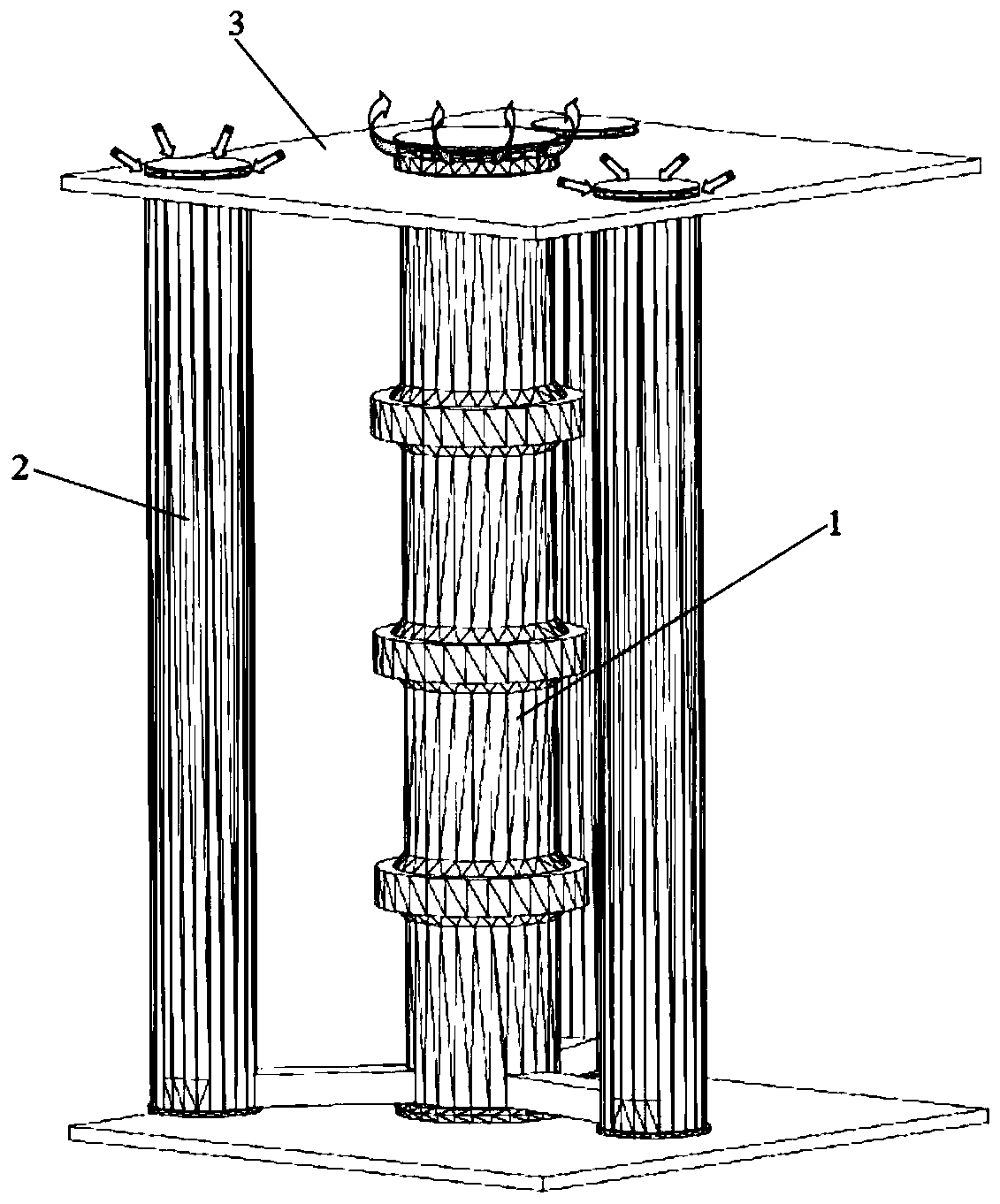
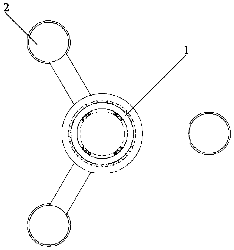
[0064] Please refer to figure 1 and figure 2 As shown, the present invention discloses a nuclear power plant spent fuel vertical storage dry well, which includes:

[0065] The concrete substrate 3 includes a surface concrete slab and an underground concrete slab buried underground, and the space between the surface concrete slab and the underground concrete slab is filled with soil and gravel;

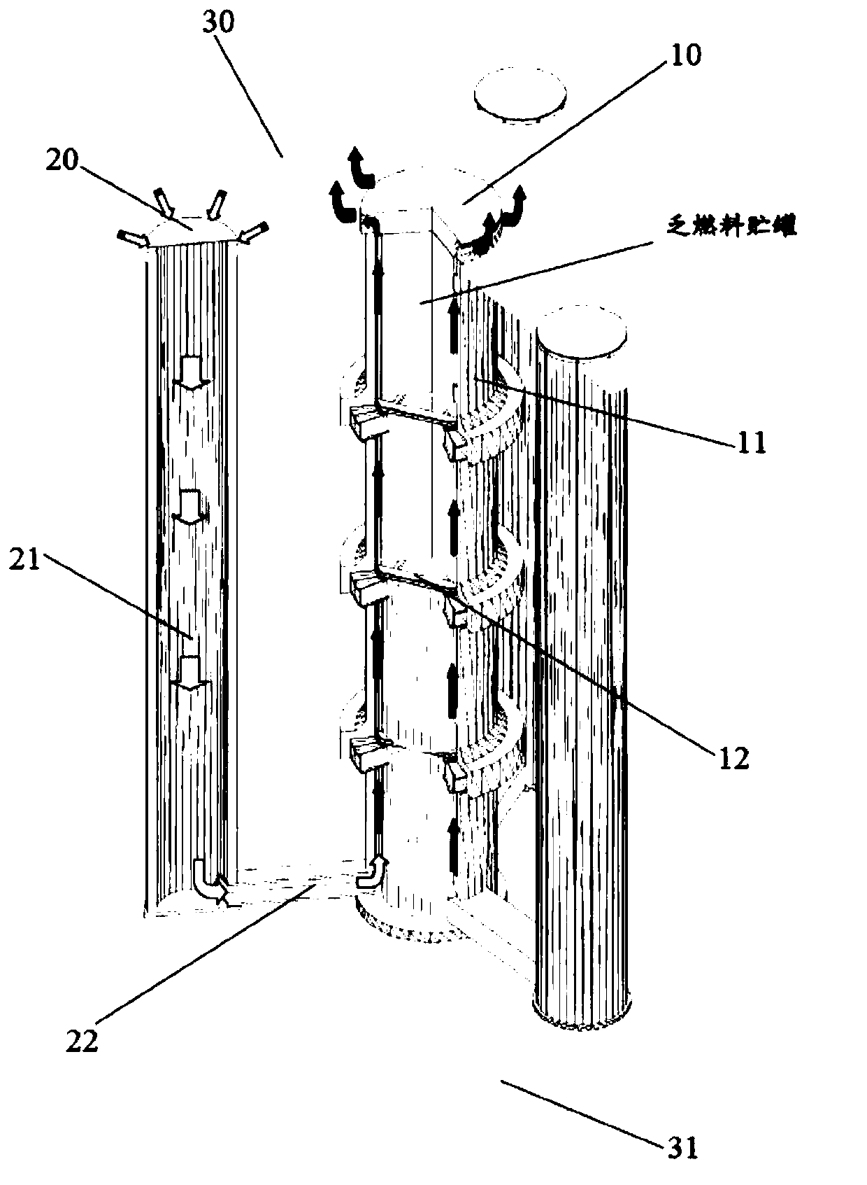
[0066] The dry well 1 is provided with a bottom on the ground concrete slab, a top air outlet on the surface concrete slab, and a dry well body 11 betwee...


PUM


Abstract

The invention discloses a nuclear power plant spent fuel vertical storage dry shaft, which comprises a concrete base plate, a dry shaft and at least one ventilation shaft surrounding the dry shaft. The concrete base plate comprises an earth surface concrete plate and an underground concrete plate buried underground. The dry shaft is provided with a bottom located on the underground concrete plate,a top air outlet located above the ground surface concrete plate, and a dry shaft body located between the bottom air outlet and the top air outlet, at least one supporting bracket is arranged in theheight direction of the dry shaft body, and a spent fuel storage tank located at the bottom of the dry shaft and at least one spent fuel storage tank located on the supporting bracket are stored in the height direction of the dry shaft body. The bottom of the ventilation shaft is located on the underground concrete plate and communicated with the dry shaft, the ventilation shaft is provided witha top air outlet communicated with the natural environment, external natural air enters the bottom of the dry shaft from the top air outlet of the ventilation shaft, and decay heat of a spent fuel assembly in the spent fuel storage tank is discharged into the surrounding environment from the top air outlet of the dry shaft.

Description

technical field [0001] The invention belongs to the technical field of nuclear power, and more specifically, the invention relates to a method for stacking and retrieving spent fuel vertical storage dry wells and spent fuel storage tanks of nuclear power plants. Background technique [0002] At present, the dry storage technology of spent fuel widely used in nuclear power plants in the world mainly adopts concrete silo technology, inside of which is a single-layer thin-walled (12mm to 14mm) shell metal storage tank for spent fuel, and the storage capacity is usually 24 groups To 37 groups of spent fuel, the weight of the entire storage tank is about 45 tons to 55 tons. Due to the thin wall thickness of the cylinder, it is necessary to configure a thick-walled concrete silo on the outside to undertake the structure and shielding protection functions. The air enters from the air inlet at the bottom of the silo and is discharged from the air outlet at the top to continuously di...

Claims


Application Information

Patent Timeline
IPC IPC(8): G21C19/19
CPCG21C19/19Y02E30/30
Inventor 程呈潘跃龙张学岭
Owner 中广核工程有限公司
Why Eureka
Try Eureka