Portable underwater lighting emergency bracelet

An underwater lighting and portable technology, which is applied in the field of lighting, can solve the problems of large emergency equipment, hinder underwater activities, and obstruct the line of sight, and achieve the effects of small and compact devices, increased waiting time for rescue, and easy portability

Inactive Publication Date: 2020-08-25
台州椒江月回户外用品科技有限公司
0 Cites 0 Cited by

AI-Extracted Technical Summary

Problems solved by technology

[0002] Human beings have a desire to explore the underwater world. When diving, they will bring some safety equipment, but some people do not like to bring safety equipment and go directly into the water. Commonly used emergency equipment is relatively large, and the sight line will be hindered after entering the...

Abstract

The invention discloses a portable underwater lighting emergency bracelet. The emergency bracelet comprises a bracelet, and a suction nozzle cavity with an upward opening is formed in the upper end inthe bracelet; an emergency oxygen mechanism is arranged in the suction nozzle cavity; an air bag cavity with a downward opening is formed in the lower end in the bracelet; an inflatable airbag mechanism is arranged in the airbag cavity; an electric lamp cavity is formed in the left end of the bracelet; an underwater lighting mechanism is arranged in the electric lamp cavity; the emergency oxygenmechanism comprises a gas cylinder cavity positioned in the right end of the bracelet; and two oxygen bottles are fixedly arranged on the right cavity wall of the gas cylinder cavity.The underwater lighting emergency bracelet is convenient to carry and small and exquisite, the lighting device capable of adjusting lamplight is provided underwater, the endurance effect is achieved through two different batteries, an oxygen device is provided when emergency circumstances happen underwater, the rescue waiting time is prolonged, people are taken away from the water through the inflation device, andthe auxiliary rescue effect is achieved.

Application Domain

Technology Topic

Electrical batteryElectric light +5

Image

  • Portable underwater lighting emergency bracelet
  • Portable underwater lighting emergency bracelet
  • Portable underwater lighting emergency bracelet

Examples

  • Experimental program(1)

Example Embodiment

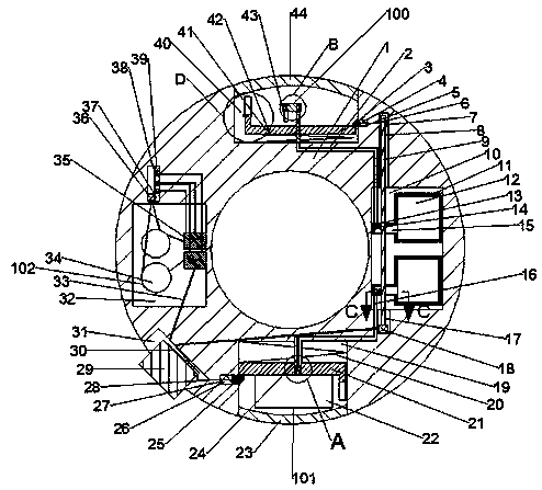
[0021] Combine below Figure 1-7 The present invention is described in detail, wherein, for the convenience of description, the orientations mentioned below are defined as follows: figure 1 The up, down, left, right, front and back directions of the projection relationship itself are the same.
[0022] combined with Figure 1-7 The portable underwater lighting emergency wristband includes a wristband 1, the inner upper end of the wristband 1 is provided with a nozzle chamber 40 with an upward opening, and an emergency oxygen mechanism 100 is arranged in the nozzle chamber 40, so that The lower end of the wristband 1 is provided with an airbag chamber 19 with an opening downward, and an inflatable airbag mechanism 101 is arranged in the airbag chamber 19, and an electric lamp chamber 32 is arranged in the left end of the wristband 1, and an electric lamp chamber 32 is arranged in the electric lamp chamber 32. The underwater lighting mechanism 102, the emergency oxygen mechanism 100 includes a gas cylinder chamber 10 located at the right end of the bracelet 1, the right chamber wall of the gas cylinder chamber 10 is fixedly provided with two oxygen cylinders 11, and the oxygen cylinder 11 An oxygen chamber 12 is provided inside, and a motor chamber 17 with an upward opening is arranged in the lower chamber wall of the gas cylinder chamber 10. There is a rotating chamber 8 with an opening downward, and the upper end of the motor 18 is connected with a motor shaft 9 whose upper end passes through the two oxygen cylinders 11 and is located in the rotating chamber 8. There is a rotating chamber 15 with an opening to the right, and two rotating blocks 14 respectively located in the two rotating chambers 15 are fixed on the motor shaft 9, and the rotating block 14 on the upper side is connected with the rotating chamber 15 on the upper side. The upper chamber wall is in contact, the lower side of the rotating block 14 is in contact with the lower chamber wall of the lower side of the rotating chamber 15, and the rotating chamber 15 and the rotating block 14 are in contact with the chamber wall. The through hole chamber 13 of the gas cylinder chamber 10, the left end of the oxygen cylinder 11 on the upper side is fixedly connected with the through hole chamber 13 on the upper side, and one end is located in the gas cylinder chamber 10 and the other end is located in the suction chamber. The elbow 2 in the mouth cavity 40, the lower end of the oxygen cylinder 11 on the lower side is fixed with a tube that communicates with the through hole cavity 13 on the lower side, and one end is located in the gas cylinder cavity 10 and the other end is located in the air bag cavity 19. Pipeline 16, the upper end of the suction nozzle cavity 40 is slidably provided with an exhalation cover 44, the lower cavity wall of the suction nozzle cavity 40 is fixedly connected with a tension spring 42, and the upper end of the tension spring 42 is fixedly connected with a moving block 41, so The upper end of the left side of the moving block 41 is slidably connected with a stretching block 58, the stretching block 58 is provided with a stretching chamber 57, and the left side of the moving block 41 is provided with a hindering chamber 60 that opens to the left. A telescopic spring 59 is fixedly connected to the right chamber wall of the cavity 60 , and the left end of the telescopic spring 59 is fixedly connected to a blocking block 61 whose left end limits the descent of the stretching block 58 .
[0023]Beneficially, the right end of the suction nozzle cavity 40 is provided with a restricting cavity 5 opening to the left, the right cavity wall of the restricting cavity 5 is fixedly connected with a compression spring 4, and the left end of the compression spring 4 is fixedly connected with a left end located at the suction nozzle. The restriction block 3 in the cavity 40, the right end of the restriction block 3 is fixedly connected with an end of the winding rope 6, the upper end of the motor shaft 9 is fixedly provided with a winding wheel 7, the other end of the winding rope 6 is connected with the winding wire The wheel 7 is fixedly connected, the suction nozzle cavity 40 is provided with a suction nozzle 48, and the upper end of the suction nozzle 48 is provided with two bite cavities 50 with one opening backward and the other opening forward, and the bite cavity 50 on the left side is 50, the rear cavity wall and the occlusal cavity 50 front cavity wall on the right side are all fixedly connected with connecting springs 62, and the other end of each of the connecting springs 62 is fixedly connected with an occlusal block 49, and the inside of the occlusal block 49 is open up and down. Through holes, two breathing chambers 51, a flow chamber 55 and a barrier chamber 52 are arranged in the lower chamber wall of each occlusion chamber 50, and the upper chamber wall of the flow chamber 55 on the left side communicates with the occlusion chamber 50 on the left side And the lower cavity wall communicates with the barrier cavity 52 on the left side, the upper cavity wall of the two breathing chambers 51 on the left side communicates with the barrier cavity 52 on the left side and the lower cavity wall communicates with the suction nozzle cavity 40, and the two breathing chambers on the right side communicate with the barrier cavity 52. The upper chamber wall of the breathing chamber 51 communicates with the occlusal chamber 50 on the right side and the lower chamber wall communicates with the barrier chamber 52 on the right side, the upper chamber wall of the flow chamber 55 on the right side communicates with the breathing chamber 51 on the right side and the lower chamber wall Connected to the nozzle cavity 40, the upper cavity wall of the barrier cavity 52 on the right side and the lower cavity wall of the barrier cavity 52 on the left side are fixedly connected with one end of a return spring 53, and the other end of the return spring 53 is fixedly connected with a The blocking block 54 in contact with the wall of the barrier cavity 52, the upper end of the elbow 2 located in the nozzle cavity 40 communicates with the flow cavity 55 on the right side, and the nozzle cavity 40 is provided with two The outlet pipe 43 of the breathing cavity 51 .
[0024] Beneficially, the inflatable air bag mechanism 101 includes a fixed spring 20 fixedly connected to the upper cavity wall of the air bag cavity 19, the lower end of the fixed spring 20 is fixedly connected with a push block 21, and the lower end of the push block 21 is fixedly provided with an air bag 22 , the push block 21 is provided with an inflatable cavity 47, the pipeline 16 is fixed on the upper end of the push block 21 and communicates with the inflatable cavity 47, and one end of the pipeline 16 is fixed to extend into the inflatable cavity 47 And there is a telescopic rod 24 with a spring inside, the lower end of the telescopic rod 24 is fixed with a gas blocking block 45, and the left and right walls of the inflatable chamber 47 are respectively fixed with a connecting block 46 located below the gas blocking block 45, The lower end of the airbag cavity 19 is slidably provided with an end cover 23, and the left end of the airbag cavity 19 is provided with a limiting cavity 26 with an opening to the right. The left cavity wall of the limiting cavity 26 is fixedly connected with a limiting spring 27, and the limiting spring The right end of 27 is connected with a limit block 25 with one end located in the airbag cavity 19 .
[0025] Beneficially, the underwater lighting mechanism 102 includes two batteries 35 fixedly connected to the right cavity wall of the lamp chamber 32, and two lamps 34 electrically connected to the batteries 35 are fixed inside the lamp chamber 32, The left end of the bracelet 1 is provided with a sliding cavity 38 located above the lamp cavity 32 and the rear cavity wall is connected to the outside. The sliding cavity 38 is provided with a sliding block 36, and the lower end of the sliding block 36 is fixed with two The lead wires 33 electrically connected with the two electric lamps 34 respectively, and the conductive chamber 37 opening to the left are arranged in the right chamber wall of the sliding chamber 38 .
[0026] Beneficially, the right cavity wall of the conductive chamber 37 is fixed with three equidistant contact switches 39, the contact switches 39 are connected to the battery 35 through wires, and the lower left side of the wristband 1 is provided with an opening outwards. Switch cavity 31, the upper right cavity wall in the switch cavity 31 is fixedly provided with a support spring 30, the other end of the support spring 30 is fixedly provided with a button 29 capable of controlling the operation of the motor 18, and the right end of the button 29 is fixedly provided with another A wire 28 with one end connected to the limiting block 25 .
[0027] Beneficially, the elastic force of the fixed spring 20 is greater than the elastic force of the inner spring of the telescopic rod 24 .
[0028] In the initial state, the rotating block 14 is located at the lower end of the through hole cavity 13, one end of the limiting block 3 is located in the limiting cavity 5 and the other end is located at the upper end of the moving block 41, the compression spring 4 is in a relaxed state, and the winding The wheel 7 is in a relaxed state, one end of the limiting block 25 is located in the limiting cavity 26 and one end is located at the upper end of the pushing block 21, the supporting spring 30 is in a relaxed state, the sliding block 36 is at the lowermost end of the sliding cavity 38, the The inner spring of the telescopic rod 24 is in a compressed state, and the fixed spring 20 and the tension spring 42 are in a compressed state.
[0029] When the sliding block 36 is pushed to move upwards and contact with the two contact switches 39, the electric lamp 34 is switched on, so that the electric lamp 34 emits light. By controlling the contact of the sliding block 36 with two different contact switches 39, the electric lamp 34 is controlled. Send out different strengths; when a person encounters an emergency underwater, press the button 29 to control the rotation of the motor 18, so that the motor shaft 9 rotates, thereby driving the winding wheel 7 to rotate, thereby winding the winding wheel 7 tightly Pull the limiting block 3 around the rope 6, so that the limiting block 3 moves to the right, so that the moving block 41 is out of the limit, so that the tension spring 42 resets and drives the moving block 41 to move upwards, thereby pushing out the exhalation cover 44, so that the suction nozzle 48 is pushed out, the motor 18 rotates, thereby driving the rotating block 14 to rotate, thereby opening the through hole chamber 13, so that the elbow 2 and the pipeline 16 are connected to the rotating chamber 15; people are biting the engaging block 49, so that the two engaging blocks 49 Move towards each other and compress the connection spring 62, so that the internal through hole of the bite block 49 communicates with the breathing chamber 51 or the flow chamber 55, thereby realizing the supply of oxygen and exhaust gas, pressing the button 29, thereby pulling the cord 28, thereby driving the limit block 25 Move to the left and compress the limit spring 27, so that the push block 21 loses its restriction and moves downward under the action of the fixed spring 20, thereby driving the airbag 22 to move downward, and the spring reset inside the telescopic rod 24 drives the telescopic rod 24 to become longer, thereby Make the air blocking block 45 and the connecting block 46 in the state of being in contact all the time, when the air bag 22 is located outside, the fixed spring 20 continues to push the pushing block 21 to move downward, and the spring reset inside the telescopic rod 24 no longer stretches the telescopic rod, Therefore, the gas blocking block 45 is separated from the connecting block 46, so that the gas in the pipeline 16 is passed into the air bag 22, and the air bag 22 expands to provide buoyancy, thereby realizing auxiliary inflation rescue.
[0030] The above-mentioned embodiments are only to illustrate the technical concept and characteristics of the present invention, and the purpose is to enable those skilled in the art to understand and implement the present invention, and not to limit the protection scope of the present invention. All equivalent changes or modifications made according to the spirit of the present invention shall fall within the protection scope of the present invention.

PUM

no PUM

Description & Claims & Application Information

We can also present the details of the Description, Claims and Application information to help users get a comprehensive understanding of the technical details of the patent, such as background art, summary of invention, brief description of drawings, description of embodiments, and other original content. On the other hand, users can also determine the specific scope of protection of the technology through the list of claims; as well as understand the changes in the life cycle of the technology with the presentation of the patent timeline. Login to view more.

Similar technology patents

Day care sleeper

Owner:GORDON GEORGE M +1

Classification and recommendation of technical efficacy words

  • Easy to carry
  • Small device

Method for preparing A type zeolite by gangue

InactiveCN1631779AThe method is simple and easySmall deviceAluminosilicate zeolite type-ACoal gangueChemistry
Owner:CHINA RES INST OF DAILY CHEM IND
Why Eureka
Try Eureka