
Screen plate structure, screening device and crushing device

A technology of sieve plate and screening unit, which is applied in the direction of sieve, solid separation, grid, etc., can solve the problems of clogging of sieve plate, reduction of porosity of sieve plate, reduction of screening efficiency, etc., so as to achieve less material blocking and high work efficiency. , the effect of improving the screening efficiency

Pending Publication Date: 2020-08-25
张潇洪
View PDF0 Cites 0 Cited by
  • Summary
  • Abstract
  • Description
  • Claims
  • Application Information

AI Technical Summary

Problems solved by technology

The small inlet of the inverted cone sieve and the large outlet will reduce the porosity of the sieve plate, and some materials will slide away from the sieve plate before passing through the sieve hole, which reduces the screening efficiency to a certain extent. Some materials will be blocked in the sieve holes. Even if the sieve plate vibrates for a long time, the materials will hardly jump out of the sieve holes, so that the sieve plate will be gradually blocked, which will further reduce the screening efficiency and cause more materials to be lost. After being screened, it slides directly from the coarse material outlet end of the vibrating screen

Method used


Image

  • Screen plate structure, screening device and crushing device
  • Screen plate structure, screening device and crushing device
  • Screen plate structure, screening device and crushing device

Examples


Embodiment Construction

[0043] In order to further explain the technical solution of the present invention, the following will be described in detail in conjunction with the examples.

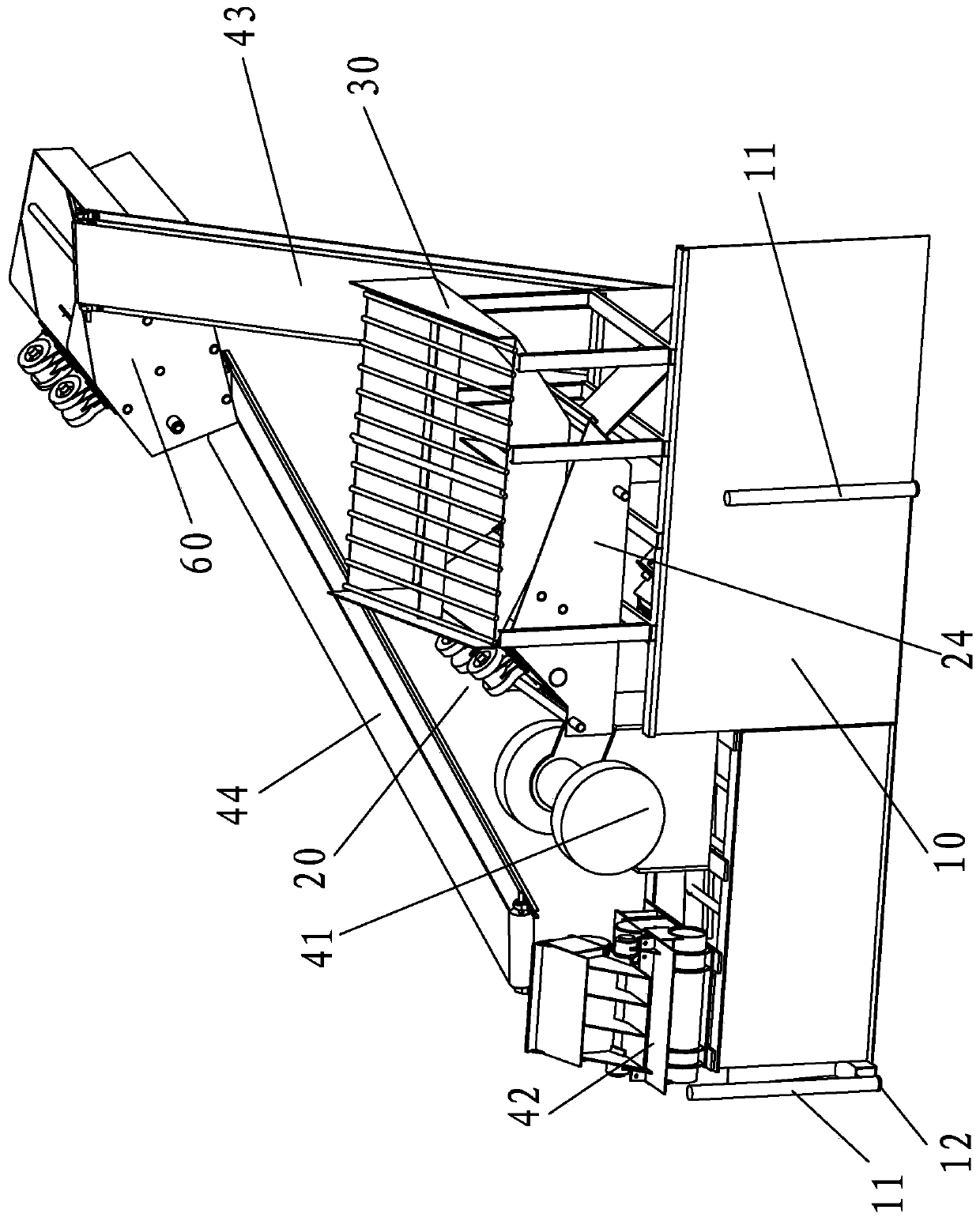
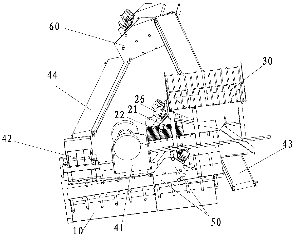
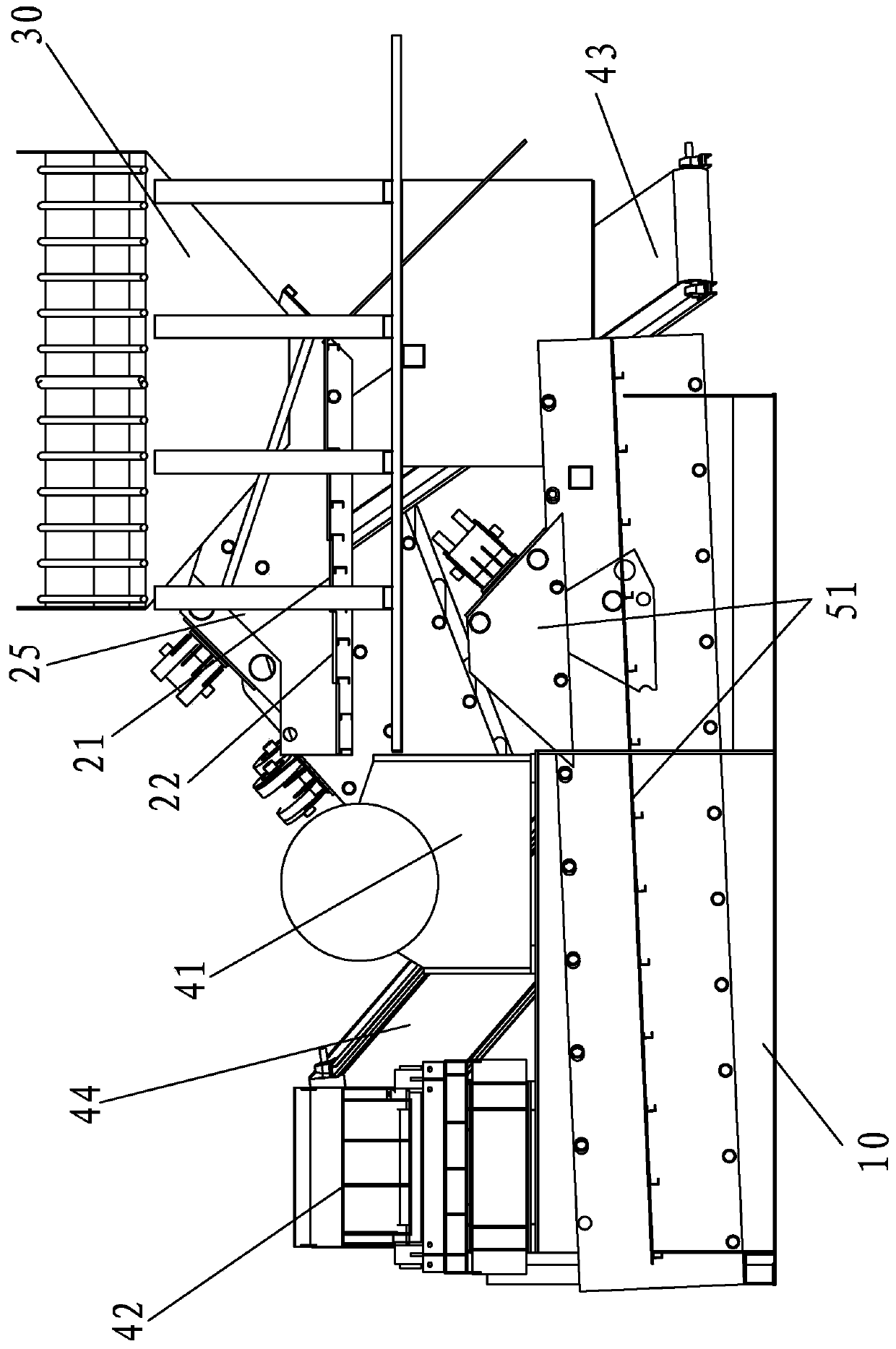
[0044] refer to Figure 1 to Figure 7 , the sieve plate structure, including a screening unit, the screening unit includes a plurality of sieve bars and connecting pieces for connecting the sieve bars into a sieve body 210, the sieve body 210 can be arranged in the horizontal direction, or can be arranged inclined relative to the horizontal plane, adjacent sieves Screening slots 215 are formed between the strips. The plurality of sieve bars at least includes a first sieve bar 213 and a second sieve bar 214 , and the plurality of sieve bars are arranged horizontally to form a sieve body 210 in the present invention. The screening groove 215 penetrates from the upper surface of the sieve body 210 to the lower surface, the first sieve bar 213 is provided with a first trough wall 2131 and a second trough wall 2132 from t...


PUM


Abstract

The invention elates to a screen plate structure. The screen plate structure comprises a screening unit, wherein the screening unit comprises a plurality of screening strips and a connector for connecting the screening strips into a screen body; a screening slot is formed between adjacent two screening strips; the screening strips at least comprise first screening strips and second screening strips; the screening slots penetrate through the lower surface of the screen body from the upper surface of the screen body; the first screening strips are provided with first slot walls and second slot walls from top to bottom; the second screening strips are provided with third slot walls and fourth slot walls from top to bottom; distance between the first slot walls and the third slot walls is gradually reduced, and the distance between the second slot walls and the fourth slot walls is gradually increased from top to bottom; acute-angle included angles between the first slot walls and the horizontal plane are smaller than those between the second slot walls and the horizontal plane; and acute-angle included angles between the third slot walls and the horizontal plane are smaller than thosebetween the fourth slot walls and the horizontal plane. The screen plate structure can improve screening efficiency, and has the advantage of being simple in structure.

Description

technical field [0001] The invention relates to a sieve plate structure, a screening device and a crushing device. Background technique [0002] Vibrating screens are mainly used to screen materials of different sizes. For some special-shaped or irregular materials, in order to increase the probability of passing through the materials, some existing vibrating screens set the sieve holes of the sieve plate into an inverted cone shape, so that the materials enter Even if it is turned over after sieving, the material is not easy to be blocked in the sieve hole. The small inlet of the inverted conical sieve hole and the big outlet will reduce the porosity of the sieve plate, and some materials will slide away from the sieve plate before passing through the sieve hole, which reduces the screening efficiency to a certain extent. Some materials will be blocked in the sieve holes. Even if the sieve plate vibrates for a long time, the materials will hardly jump out of the sieve hole...

Claims


Application Information

Patent Timeline
Patent Type & Authority Applications(China)
IPC IPC(8): B07B1/28B07B1/46B02C21/00B02C23/14B02C23/16
CPCB02C21/00B02C23/14B02C23/16B02C2023/165B07B1/28B07B1/46B07B1/4609
Inventor 张潇洪张春瑜
Owner 张潇洪
Learn More