Steel bar welding position correction device

A technology for calibration and steel bars, which is applied in the field of steel bar welding calibration devices, can solve problems that affect the alignment of welding points, reduce welding quality, and welding errors, and achieve the effects of improving production efficiency, facilitating manufacturing and maintenance, and improving positioning accuracy

Active Publication Date: 2020-08-25
SHAODONG INTELLIGENT MFG INNOVATIVE INST
View PDF5 Cites 0 Cited by
  • Summary
  • Abstract
  • Description
  • Claims
  • Application Information

AI Technical Summary

Problems solved by technology

Due to the large size of the steel pipe and the steel bar, usually more than 10 meters, it is easy to deviate from the position during the feeding process of the steel bar, and the M-shaped steel bar will also produce a certain elastic deformation when it is transported, which will affect the alignment of the welding points, resulting in Obvious welding errors, reducing welding quality

Method used


Image

  • Steel bar welding position correction device
  • Steel bar welding position correction device
  • Steel bar welding position correction device

Examples


Embodiment Construction

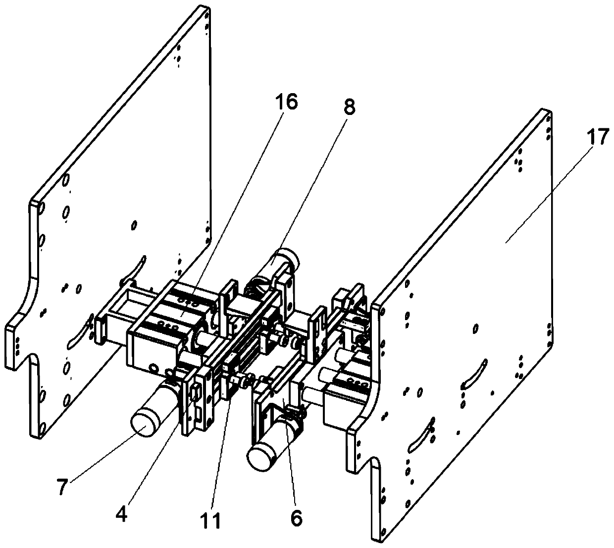
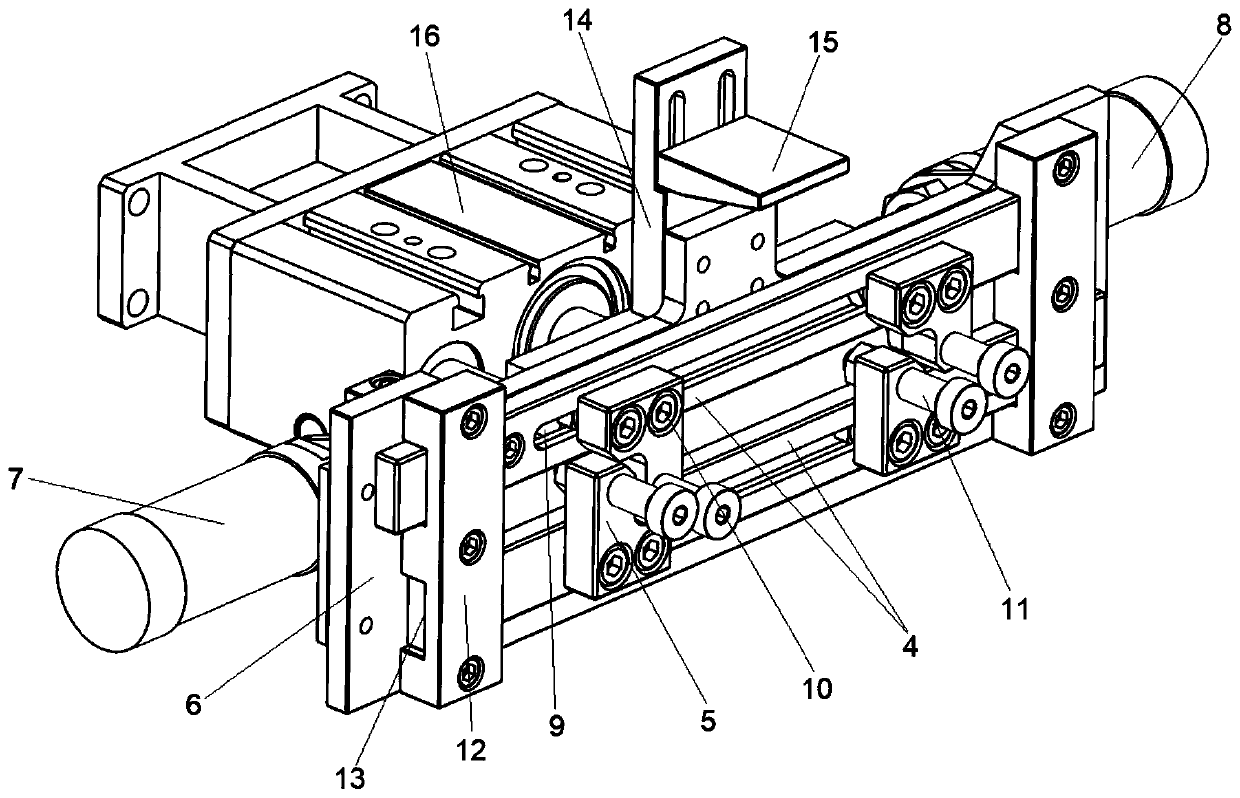
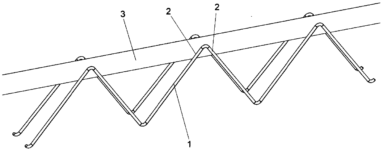
[0022] In order to make the technical problems, technical solutions and advantages to be solved by the present invention clearer, the following will describe in detail with reference to the drawings and specific embodiments. Apparently, the described embodiments are some, but not all, embodiments of the present invention. Based on the embodiments of the present invention, all other embodiments obtained by persons of ordinary skill in the art without making creative efforts belong to the protection scope of the present invention. In addition, the technical features involved in the different embodiments of the present invention described below may be combined with each other as long as there is no conflict with each other.

[0023] Such as Figure 1-Figure 3 As shown, the embodiment of the present invention provides a rebar welding calibration device, including a first calibration structure, a second calibration structure and a top limit structure. Wherein the first calibratio...


PUM


Abstract

The invention provides a steel bar welding position correction device. The steel bar welding position correction device comprises a first position correction structure, a second position correction structure and a top end limiting structure. The first position correction structure and the second position correction structure are arranged oppositely and can horizontally slide face to face. The first position correction structure and the second position correction structure are both provided with position correction parts. The position correction parts get close to each other to clamp and locatetwo welding spots of steel bars. The top end limiting structure is arranged between the first position correction structure and the second position correction structure and used for limiting the vertical positions of top protrusions of the steel bars. Through cooperation of the two matched position correction structures and the top end limiting structure, the steel bar welding position correctiondevice automatically complete correction of the two welding spots of the steel bars to enable the welding spots of the steel bars to be aligned with the welding positions of a steel tube, the locating precision of the welding spots and the automatic welding accuracy and quality of a truss are improved,

Description

technical field [0001] The invention relates to the technical field of steel bar processing and welding, in particular to a steel bar welding calibration device. Background technique [0002] A truss is a support structure widely used in large-scale transportation buildings such as houses, bridges, and ships. A truss composed of straight rods generally has a planar or spatial frame form of triangular units. The straight bar of the truss mainly bears axial tension or pressure, which can make full use of the strength of the material, while the web bar usually adopts a steel bar structure. The web bar of this steel bar structure is usually M-shaped, such as image 3 As shown, the steel bars of this shape can form a triangular structure in the truss structure, thereby bearing greater bending stress. The production of such trusses requires the welding of steel bars to steel pipes used as straight rods. [0003] In the prior art, the automatic welding of the steel bar and the mai...

Claims


Application Information

Patent Timeline
Patent Type & Authority Applications(China)
IPC IPC(8): B23K37/04
CPCB23K37/0443
Inventor 彭刚单常清王友文
Owner SHAODONG INTELLIGENT MFG INNOVATIVE INST
Why Eureka
Try Eureka