Hybrid power transmission

A hybrid and transmission technology, applied in hybrid vehicles, power units, pneumatic power units, etc., can solve the problems of reducing auxiliary motors or drive motors, development limitations of pure electric cars, unreasonable transmission mechanism layout, etc. Reduce the axial space occupied, facilitate the installation of the whole vehicle, and light weight

Pending Publication Date: 2020-08-25
吉泰车辆技术(苏州)有限公司
View PDF0 Cites 0 Cited by
  • Summary
  • Abstract
  • Description
  • Claims
  • Application Information

AI Technical Summary

Problems solved by technology

[0003] ①Traditional powertrain technology mainly focuses on reducing engine emissions and improving engine efficiency, but improving engine technology alone can no longer meet increasingly stringent emission regulations, and new breakthroughs need to be found;
[0004] ②Although pure electric vehicles can achieve zero emissions and meet the requirements of any emission regulations, the research and development of electric vehicles involves many key technologies, such as batteries and battery control, high-performance motors, and integrated vehicle control. It is still immature, and limited by factors such as high battery cost, few charging and discharging cycles, and short vehicle mileage, the development of pure electric cars will be greatly restricted in a short period of time
[0007] (1) Due to the position limitation of the differential, input shaft, etc., and the unreasonable layout of the transmission mechanism, the additional driving motor and the main driving motor adopt two different models, one is a high-speed and high-efficiency motor, and the other is It is a high-torque low-speed motor, which causes the production cost of the entire transmission to be too high;
[0008] (2) Because most of the two-speed transmission system adopts a synchronizer structure, power interruption occurs, otherwise the gear cannot be shifted. At the same time, the existing products are basically arranged on the same axis, so they occupy a large axial space;
However, the wheelbase of the dual-mass flywheel is large, and the space in the transmission is limited, so it is bound to reduce the volume of the auxiliary motor or the driving motor, and reduce the power of the motor.

Method used


Image

  • Hybrid power transmission

Examples


Embodiment Construction

[0035] The present invention will be described in detail below in conjunction with specific embodiments shown in the accompanying drawings. However, these embodiments are not limited to the present invention, and structural, method, or functional changes made by those skilled in the art according to these embodiments are included within the protection scope of the present invention.

[0036] In describing the present invention, it should be understood that the terms "center", "longitudinal", "transverse", "upper", "lower", "front", "rear", "left", "right", " The orientations or positional relationships indicated by "vertical", "horizontal", "top", "bottom", "inner" and "outer" are based on the orientations or positional relationships shown in the drawings, and are only for the convenience of describing the present invention and Simplified descriptions, rather than indicating or implying that the device or element referred to must have a particular orientation, be constructed a...


PUM


Abstract

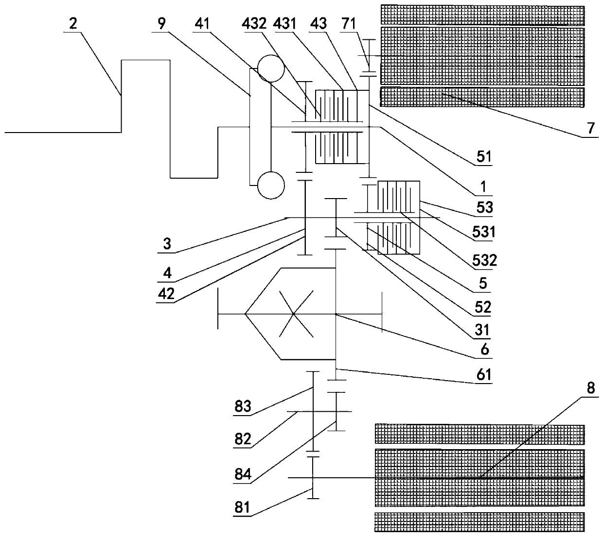
The invention discloses a hybrid power transmission which at least comprises an input shaft and an output shaft which are arranged in parallel. The input shaft and the output shaft are in transmissionconnection through a gear pair I and a gear pair II, and the output shaft is further provided with a differential mechanism in transmission connection with the output shaft. An auxiliary motor and amain driving motor are further included, the auxiliary motor is mechanically and directly connected with the engine, and electric power is transmitted to the differential mechanism through the gear pair II; and the main driving motor is directly connected with the differential mechanism and transmits the electric power to the differential mechanism, and the auxiliary motor and the main driving motor are high-speed, efficient and long-wheelbase motors with the same wheelbase. The hybrid power transmission has advantages that cost is reduced, a double-shaft design is adopted to reduce an axial occupied space of the gear pair, the auxiliary motor is mechanically and directly connected to the engine to provide inertia needed by the engine, and a damping disc is used in cooperation to reduce anaxial occupied space.

Description

technical field [0001] The present invention relates to the technical field of electric vehicles, in particular to the technical field of gearboxes, specifically a hybrid transmission. Background technique [0002] With the worldwide energy shortage and emission regulations restricting vehicle carbon emissions, safety, energy saving and environmental protection have become the themes of modern automobile development. At the same time, the traditional internal combustion engine can no longer meet the emission requirements, and new energy vehicles such as pure electric vehicles and fuel cell vehicles are restricted by the bottleneck of key technologies, and it is difficult to break through in a short time. Specifically in: [0003] ①Traditional powertrain technology mainly focuses on reducing engine emissions and improving engine efficiency, but improving engine technology alone can no longer meet increasingly stringent emission regulations, and new breakthroughs need to be f...

Claims


Application Information

Patent Timeline
Patent Type & Authority Applications(China)
IPC IPC(8): B60K6/547B60K6/36B60K6/38B60K6/48B60K6/26
CPCB60K6/26B60K6/36B60K6/38B60K6/48B60K6/547B60K2006/268Y02T10/62
Inventor 惠无垠姜旭义梁志海
Owner 吉泰车辆技术(苏州)有限公司
Why Eureka
Try Eureka