Eureka AIR delivers breakthrough ideas for toughest innovation challenges, trusted by R&D personnel around the world.

Continuous production system and production method of polysiloxane

A technology of polysiloxane and production system, applied in the field of continuous production system of polysiloxane, can solve the problems of high viscosity, yellowing of cross-linking, insufficient stirring, etc.

Active Publication Date: 2020-08-25
ZHEJIANG XINAN CHEM INDAL GROUP
View PDF9 Cites 2 Cited by
  • Summary
  • Abstract
  • Description
  • Claims
  • Application Information

AI Technical Summary

Problems solved by technology

This preparation method has the following defects: 1) It has high requirements on the stirring system. As the viscosity of the polymer increases, the fluidity becomes poor, resulting in insufficient stirring, resulting in local overheating, crosslinking or yellowing
2) High viscosity, not easy to unload
[0004] Chinese patent application number 201310331091.2, the invention title is "The production method and production system of twin-screw continuous production of 107 rubber", which discloses that dimethylcyclosiloxane is dehydrated in a dehydration kettle, mixed with a static mixer to disperse the catalyst, and in a degrader Degradation, continuous production of 50,000 cp107 glue by screw devolatilization and discharge. In this patent, the screw machine devolatilizes the discharge, but the volatile matter produced is relatively high
Chinese Patent Application No. 200910193006.1, the invention name is "A Method for Preparation of Ultra-high Molecular Weight Polyorganosiloxane", which discloses a reactor with S-type stirring, with dimethylcyclosiloxane or α, ω -Dihydroxypolydimethylsiloxane is used as raw material to prepare ultra-high molecular weight polysiloxane in batches, and the volatile matter produced is also relatively high

Method used

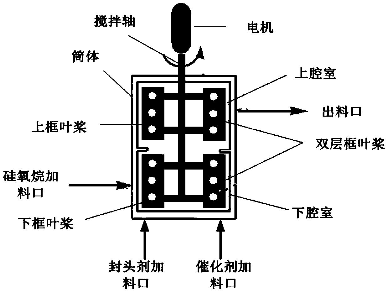
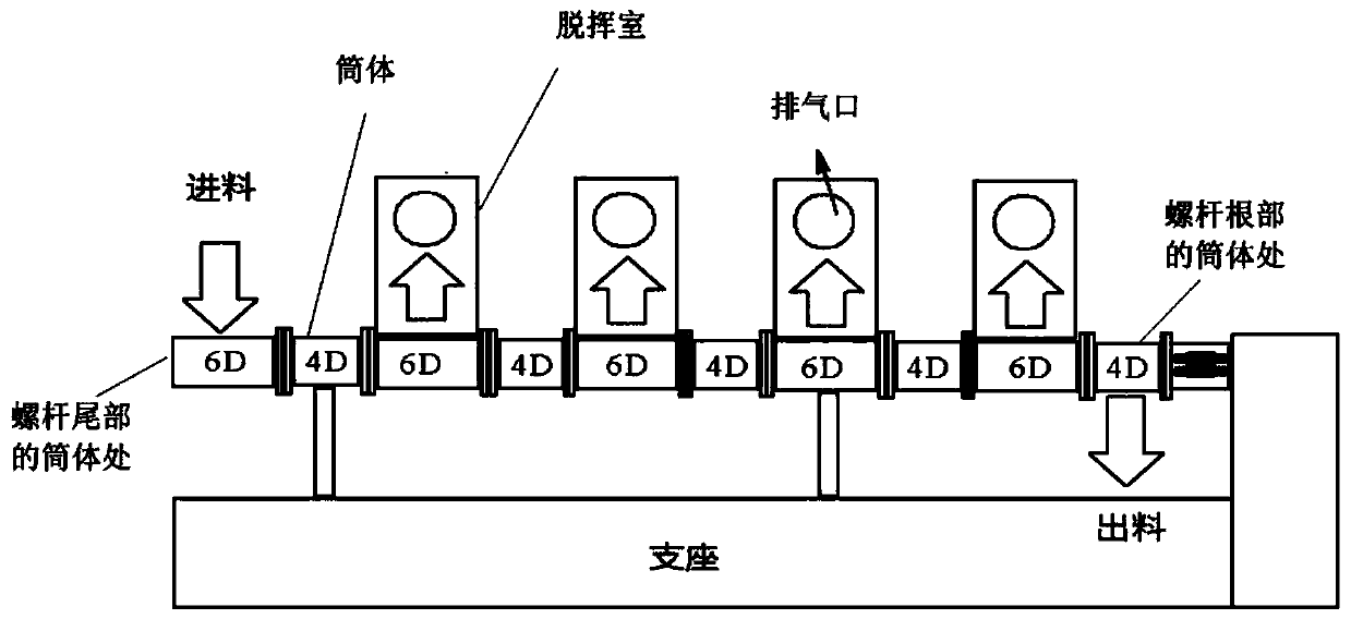

Image

  • Continuous production system and production method of polysiloxane
  • Continuous production system and production method of polysiloxane
  • Continuous production system and production method of polysiloxane

Examples


Embodiment 1

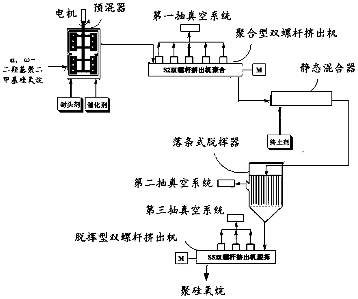
[0142] This embodiment provides a figure 1 The continuous production system of polysiloxane shown includes:

[0143] premixer;

[0144] A polymeric twin-screw extruder connected to the outlet of the premixer;

[0145] A first vacuum pump connected to the exhaust port of the polymeric twin-screw extruder;

[0146] A static mixer connected to the outlet of the polymerization type twin-screw extruder;

[0147] A drop strip type devolatilizer connected to the discharge port of the static mixer;

[0148] The second vacuum pump that links to each other with the vacuum port of described drop bar type devolatilizer;

[0149] The devolatilization type twin-screw extruder that links to each other with the discharge port of described drop bar type devolatilizer;

[0150] The third vacuum pump connected with the vacuum port of the devolatilization type twin-screw extruder;

[0151] A cooling device connected to the outlet of the devolatilization type twin-screw extruder;

[0152] A...

Embodiment 2

[0180] This embodiment provides a figure 1 The continuous production system of polysiloxane shown includes:

[0181] premixer;

[0182] A polymeric twin-screw extruder connected to the outlet of the premixer;

[0183] A first vacuum pump connected to the exhaust port of the polymeric twin-screw extruder;

[0184] A static mixer connected to the outlet of the polymerization type twin-screw extruder;

[0185] A drop strip type devolatilizer connected to the discharge port of the static mixer;

[0186] The second vacuum pump that links to each other with the vacuum port of described drop bar type devolatilizer;

[0187] The devolatilization type twin-screw extruder that links to each other with the discharge port of described drop bar type devolatilizer;

[0188] The third vacuum pump connected with the vacuum port of the devolatilization type twin-screw extruder;

[0189] A cooling device connected to the outlet of the devolatilization type twin-screw extruder;

[0190]A ...

Embodiment 3

[0208] This embodiment provides a figure 1 The continuous production system of polysiloxane shown includes:

[0209] premixer;

[0210] A polymeric twin-screw extruder connected to the outlet of the premixer;

[0211] A first vacuum pump connected to the exhaust port of the polymeric twin-screw extruder;

[0212] A static mixer connected to the outlet of the polymerization type twin-screw extruder;

[0213] A drop strip type devolatilizer connected to the discharge port of the static mixer;

[0214] The second vacuum pump that links to each other with the vacuum port of described drop bar type devolatilizer;

[0215] The devolatilization type twin-screw extruder that links to each other with the discharge port of described drop bar type devolatilizer;

[0216] The third vacuum pump connected with the vacuum port of the devolatilization type twin-screw extruder;

[0217] A cooling device connected to the outlet of the devolatilization type twin-screw extruder;

[0218] A...


PUM

PropertyMeasurementUnit
Heightaaaaaaaaaa
Viscosityaaaaaaaaaa

Abstract

The invention relates to the technical field of silicone rubber production and relates a continuous production system and method of polysiloxane. The continuous production system for polysiloxane comprises a premixer, a polymerization type double-screw extruder connected with a discharge hole of the premixer, a first vacuumizing system connected with an exhaust port of the polymerization type double-screw extruder, a static mixer connected with a discharge hole of the polymerization type double-screw extruder, a falling strip type devolatilization device connected with a discharge hole of thestatic mixer, a second vacuumizing system connected with a vacuum hole of the strip falling type devolatilization device, a devolatilization type double-screw extruder connected with a discharge holeof the strip falling type devolatilization device, and a third vacuumizing system connected with a vacuum port of the devolatilization type double-screw extruder. Finally, the produced polysiloxane isrelatively high in viscosity and relatively low in volatile component.

Description

technical field [0001] The invention relates to the technical field of silicone rubber production, in particular to a continuous production system and production method of polysiloxane. Background technique [0002] On June 27, 2018, the European Chemicals Agency (ECHA) officially announced the addition of the 19th batch of 10 SVHC lists on its official website, including D 4 、D 5 and D 6 Included as Substances of High Concern, each individual content is required to be less than 0.1%. As the requirements for the level of environmental and health protection become higher and higher, reducing the potential risks of D4, D5 and D6 and providing risk reduction measures will transfer more to the manufacturers. [0003] The synthesis of ultra-high viscosity polysiloxane mostly adopts a catalytic equilibrium process, and the equipment used is a polymerization kettle. In order to obtain ultra-high viscosity polysiloxane, it is generally achieved by prolonging the polymerization t...

Claims


Application Information

Patent Timeline
IPC IPC(8): C08G77/08C08G77/06C08G77/34
CPCC08G77/06C08G77/08C08G77/34
Inventor 郑智刘继朱晓英
Owner ZHEJIANG XINAN CHEM INDAL GROUP
Why Eureka
Eureka Blog
Learn More