Turbocharger

A technology for turbochargers and turbine housings, which is applied in the direction of machines/engines, liquid fuel engines, mechanical equipment, etc., and can solve problems such as large impact force of the valve cover 16, unevenness on both sides, and impact on sealing, so as to avoid panting vibration, avoiding excessive idle time, and improving compression efficiency

Inactive Publication Date: 2020-08-25
CHANGZHOU E&E TURBO POWER
View PDF10 Cites 5 Cited by
  • Summary
  • Abstract
  • Description
  • Claims
  • Application Information

AI Technical Summary

Problems solved by technology

A well-matched supercharger will generally not be blocked, but the cost of a well-matched supercharger will increase a lot. In addition, when the working conditions change, such as channel blockage, too high or too low load, uneven diesel engine load, and load In case of sudden change, even a well-matched supercharger will have surge
[0005] The surge of the turbocharger occurs in the compressor part (the impeller of the compressor), and the specific hazards include noise and damage to the shafting parts of the turbocharger; the engine works rough, and when working in the surge area, the work is unstable and shakes, etc.
[0006] In addition, because the pressure relief valve has been in a high-temperature working environment for a long time and the switch is frequent, the valve and the turbine casing 1 are in contact with each other, and the bypass valve is easy to wear and is one of the parts that are most likely to be damaged at the turbine end.
like Figure 15 As shown, in the pressure relief valve structure of the turbocharger in the prior art, the valve plate and the pressure relief port are in plane-to-plane contact. When the valve cover 16 is opened, the airflow flowing out through the pressure relief port 1b appears as The two sides of the valve cover are uneven, and the impact force on the valve cover 16 is relatively large
In a high temperature environment, it is easy to cause the riveted part of the rocker arm 15 and the valve cover 16 to fall off
At the same time, because the valve cover 16 is frequently closed, the valve cover 16 is easy to wear and tear, which affects the sealing
In addition, when the valve of the ordinary supercharger is opened and the gas is bypassed, there will be a lot of noise

Method used


Image

  • Turbocharger
  • Turbocharger
  • Turbocharger

Examples


Embodiment Construction

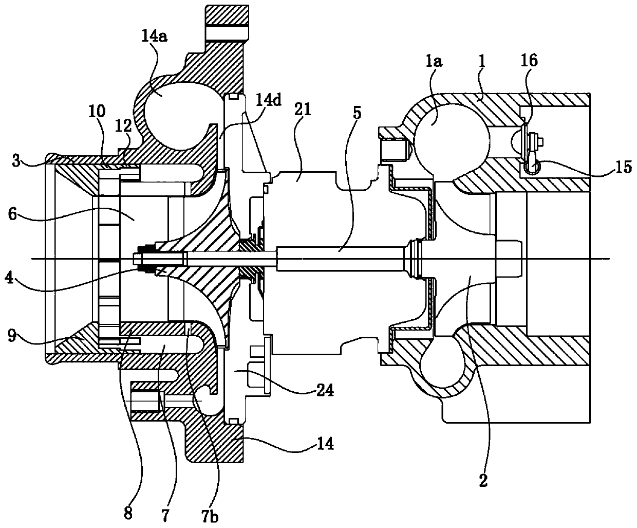
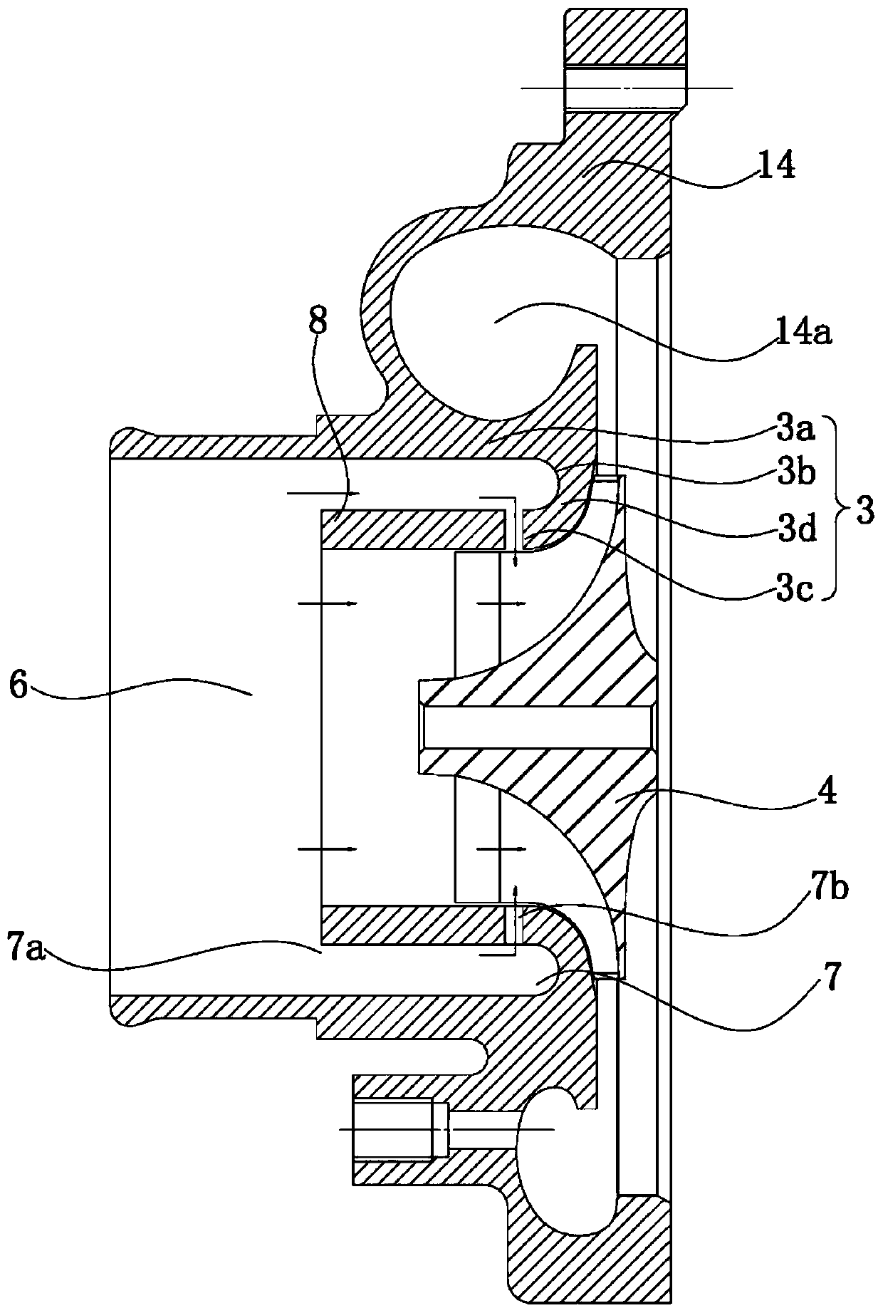
[0043] Such as figure 1 , the turbocharger of the present invention includes a turbine casing 1 with an exhaust gas passage 1a, a turbine impeller 2, a compressor casing, a compressor impeller 4, a rotating shaft 5, an intermediate casing 21, a shaft seal sleeve 26, and a first sealing ring 25 , the second sealing ring 27, the turbine casing 1 is fixed to one end of the middle casing, the compressor casing is fixed to the other end of the middle casing 21, the turbine impeller 2 is located in the exhaust gas channel 1a of the turbine casing 1 and fixed to the rotating shaft 5, The rotating shaft 5 passes through the middle shell, and the compressor impeller 4 is fixed to the rotating shaft 5 . The compressor housing includes a cylinder and a flow channel housing 14 fixed to the cylinder. The compressor housing also includes a diffuser back plate 24 , and the diffuser back plate 24 is fixed to the flow channel housing 14 .

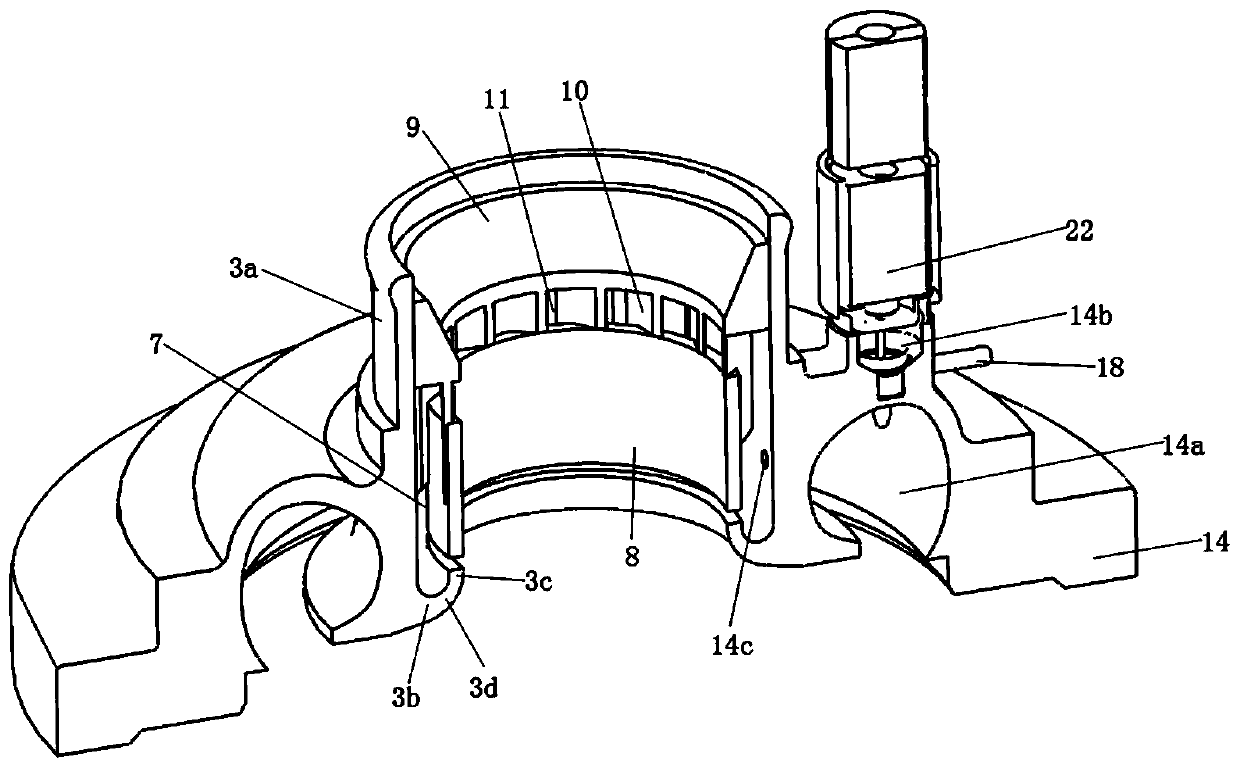
[0044] Such as figure 1 with figure 2 , The flo...


PUM


Abstract

The invention discloses a turbocharger. The turbocharger is characterized in that a compressor casing comprises a cylinder body and a flow channel casing fixed to the cylinder body, a gas conveying flow channel is formed in the flow channel casing, a gas conveying channel is formed in the cylinder body, the gas conveying channel comprises a main gas conveying channel, a bypass gas guide part, a first gas conveying opening and a second gas conveying opening, wherein the axial direction of the main gas conveying channel is parallel to the axial direction of a compressor impeller, the compressorimpeller is located in the main gas conveying channel, the bypass gas guide part is located around the main gas conveying channel and the gas compressor impeller, the first gas conveying opening and the second gas conveying opening are located in the two ends of the bypass gas guide part respectively, the second gas conveying opening communicates with the main gas conveying channel, and the gas outlet direction of the second gas conveying opening is not perpendicular to the radial direction of the gas compressor impeller; and when the turbocharger is in a normal working state, gas flow entering the bypass gas guide part from the first gas conveying opening enters the gas compressor impeller to be compressed after flowing out from the second gas conveying opening. The turbocharger has the advantages that the gas compression efficiency is improved, and surge of the turbocharger is avoided.

Description

technical field [0001] The invention relates to a turbocharger. Background technique [0002] Such as Figure 14 , the existing turbocharger comprises a turbine casing 1, a turbine wheel 2, a compressor casing, a compressor wheel 4, a rotating shaft 5, and an intermediate casing 21, and one end of the turbine casing 1 and the intermediate casing 21 is fixed, and the compressor casing Fixed with the other end of the middle casing 21, the turbine impeller 2 is located in the turbine casing 1 and fixed with the rotating shaft 5, the rotating shaft 5 passes through the middle casing 21, and the compressor impeller 4 is fixed with the rotating shaft 5 (compressor casing and compressor The impeller and the rotating shaft form the air compressor), and the air compressor housing has an air delivery channel and a diffuser channel 14d. Rotating compressor impeller 4, turbine impeller 2, and rotating shaft 5, shaft seal sleeve 6 and impeller lock nut that are connected between the two...

Claims


Application Information

Patent Timeline
Patent Type & Authority Applications(China)
IPC IPC(8): F02B37/00F02B37/18F02B39/16F04D29/42F04D29/66
CPCF02B37/00F02B37/18F02B39/16F04D29/4226F04D29/667Y02T10/12
Inventor 阮新豪唐云冰谢小虎
Owner CHANGZHOU E&E TURBO POWER
Why Eureka
Try Eureka