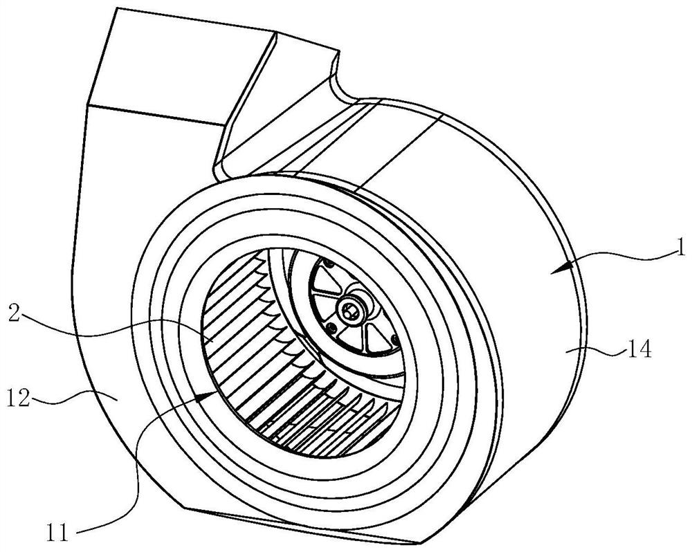
a centrifugal fan

A centrifugal fan and air inlet technology, which is applied in the field of power system, can solve the problems of increased leakage flow, decreased impeller working ability, low speed, etc., and achieve the effects of avoiding vortex, improving rectification efficiency and reducing noise

Active Publication Date: 2022-02-18
NINGBO FOTILE KITCHEN WARE CO LTD
View PDF6 Cites 0 Cited by
  • Summary
  • Abstract
  • Description
  • Claims
  • Application Information

AI Technical Summary

Problems solved by technology

[0004] In the existing multi-blade centrifugal fan system, there are certain problems in the cooperation between the collector and the impeller: when the axial clearance is too small, the airflow cannot quickly change from axial to radial flow after entering the impeller, so that the impeller The low-speed vortex flow is formed at the front end, and the working ability of the impeller decreases; when the axial clearance is increased appropriately, although the airflow entering the impeller can better complete the change of the speed direction, the low-speed vortex flow can be reduced, and the working ability of the front end of the impeller can be improved. The leakage flow between the diffuser and the impeller will increase slightly, and the working ability of the impeller will also decrease

Method used


Image

  • a centrifugal fan
  • a centrifugal fan
  • a centrifugal fan

Examples


Embodiment Construction

[0020] Embodiments of the present invention are described in detail below, examples of which are shown in the drawings, wherein the same or similar reference numerals denote the same or similar elements or elements having the same or similar functions.

[0021] In describing the present invention, it should be understood that the terms "center", "longitudinal", "transverse", "length", "width", "thickness", "upper", "lower", "front", " Back", "Left", "Right", "Vertical", "Horizontal", "Top", "Bottom", "Inner", "Outer", "Clockwise", "Counterclockwise", "Axial", The orientation or positional relationship indicated by "radial", "circumferential", etc. is based on the orientation or positional relationship shown in the drawings, and is only for the convenience of describing the present invention and simplifying the description, rather than indicating or implying the referred device or element must have a particular orientation, be constructed, and operate in a particular orientatio...


PUM


Abstract

The invention discloses an impeller, which includes a front ring, a rear ring and blades arranged between the front ring and the rear ring. The inclined plane gradually extends toward the direction close to the rear circle from the inlet end to the outlet end of the blade. Also disclosed is a centrifugal fan which should have the above-mentioned impeller. Compared with the prior art, the present invention has the advantages that: the chamfering of the blades at the junction with the front ring can eliminate the low-speed vortex flow formed at the front end of the impeller; the section of the axial guide part of the collector is arc-shaped, which can The direction of the airflow entering the impeller is changed to improve the rectification efficiency; the projection of the oblique cutting of the blade is in line with the tangent of the corresponding part of the collector, which can ensure that the airflow leaving the collector enters the impeller along the trend, avoiding that when the airflow turns The flow leakage between the vortex formed at the collector and the impeller.

Description

technical field [0001] The invention relates to a power system, in particular to an impeller and a centrifugal fan using the impeller. Background technique [0002] The multi-blade centrifugal fan has the characteristics of high pressure and low noise. Therefore, the current society generally uses the multi-blade centrifugal fan system as the power source, and uses the high-speed rotating impeller to complete the two functions of acting and filtering in the volute. As it is commonly used in range hoods, the oil smoke is sucked and exhausted through the multi-blade centrifugal fan installed inside the range hood. The multi-blade centrifugal fan includes a volute, an impeller installed in the volute and a motor that drives the impeller to rotate. When the impeller rotates, the The center of the fan generates negative pressure suction, sucking the fumes under the range hood into the fan, and after being accelerated by the fan, it is collected by the volute and guided out of the...

Claims


Application Information

Patent Timeline
Patent Type & Authority Patents(China)
IPC IPC(8): F04D29/28F04D29/30F04D29/66F04D29/42F04D29/44F04D17/16F04D25/08
CPCF04D29/283F04D29/30F04D29/667F04D29/666F04D29/663F04D29/4233F04D29/441F04D17/16F04D25/08
Inventor 余旭锋时璐璐马志豪
Owner NINGBO FOTILE KITCHEN WARE CO LTD
Why Eureka
Try Eureka