Side-spraying combustor

A technology of burners and combustion cylinders, applied in the direction of burners, gas fuel burners, combustion ignition, etc., can solve the problems of large volume of incinerators, production of NO compounds, environmental pollution, etc., and achieve the effect of large combustion area and sufficient combustion

Active Publication Date: 2020-08-25
浙江亿得利燃烧器有限公司
View PDF14 Cites 3 Cited by
  • Summary
  • Abstract
  • Description
  • Claims
  • Application Information

AI Technical Summary

Problems solved by technology

[0004] There are the following defects in the above-mentioned existing technical solutions: the existing incinerator has a relatively large volume, and the front end of the combustion tube is installed in the incinerator, and the flame is toward the Injection from the front will make the space around the combustion cylinder form a blind area, which cannot be directly sprayed by the flame, resulting in the incomplete combustion of the atomized test solution in the blind area, and insufficient combustion will produce NO compounds, causing environmental pollution

Method used


Image

  • Side-spraying combustor
  • Side-spraying combustor
  • Side-spraying combustor

Examples


Embodiment Construction

[0033] The present invention will be described in further detail below in conjunction with the accompanying drawings.

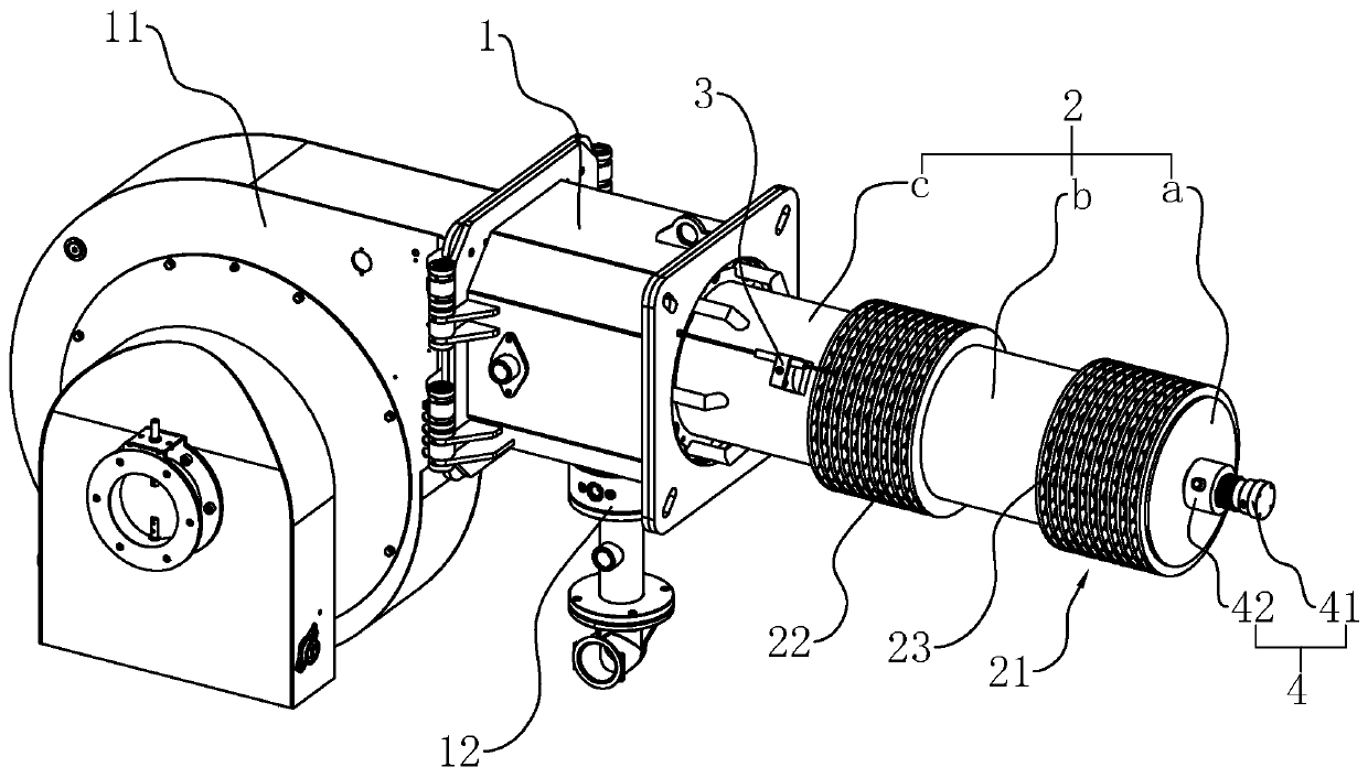
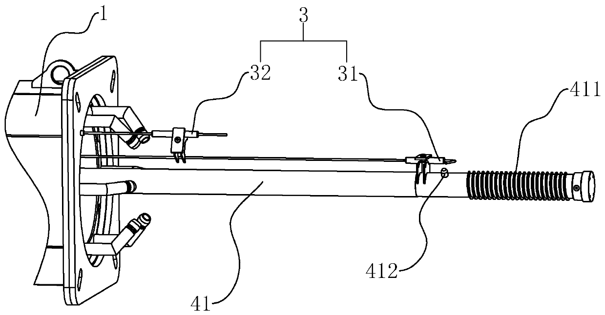
[0034] This embodiment discloses a side injection burner, such as figure 1 As shown, it includes a burner main body 1 , a combustion tube 2 is provided at one end of the burner main body 1 , and an air inlet device 11 and a gas valve group 12 are provided at the other end. The combustion tube 2 is installed in the incinerator, the gas valve group 12 is used to feed gas into the burner body 1, and the air inlet device 11 is used to feed air into the burner body 1, and the gas is mixed and brought into the combustion tube 2 .

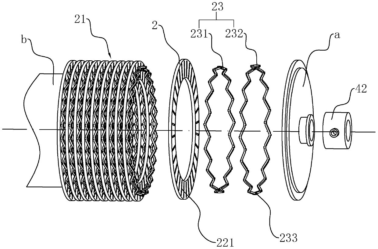
[0035] Such as figure 1 , figure 2 As shown, the front end of the combustion tube 2 is closed, and the combustion tube 2 is provided with two front and rear combustion ports 21 surrounding the circumference. The two combustion ports 21 divide the combustion tube 2 into mutually independent front section a, middle section b and The r...


PUM


Abstract

The invention relates to the technical field of combustors, and aims to provide a side-spraying combustor. The side-spraying combustor comprises a combustor body, wherein a combustion cylinder is arranged at one end of the combustor body, and an air inlet device and a gas valve set are arranged at the other end of the combustor body; an ignition device for igniting fuel gas is arranged on the combustion cylinder; the front end of the combustion cylinder is closed, and combustion openings formed in the circumferential direction in a surrounding mode is formed in the side wall of the combustioncylinder. According to the side-spraying combustor, gas and air are introduced into the combustion cylinder through the air inlet device and the gas valve set, and then the gas and the air are jettedtowards the periphery in the radial direction through the combustion openings, so that the atomized test solution in the large area around the combustion cylinder is combusted through ignited flame, the combustion area is large, and combustion is more sufficient.

Description

technical field [0001] The invention relates to the technical field of burners, in particular to a side injection burner. Background technique [0002] Burners are collectively referred to as devices that allow fuel and air to be sprayed and mixed in a certain way. Burners are divided into industrial burners, burners, civil burners, and special burners according to their types and application fields. The function of the burner is to atomize the sample through flame combustion: the atomized test solution enters the burner, and under the action of the flame temperature and flame atmosphere, it undergoes drying, melting, evaporation, dissociation and other processes to produce a large number of ground state atoms. And some excited state atoms, ions and molecules. [0003] At present, the Chinese patent document with the authorized announcement number CN207407340U in the prior art discloses a low-nitrogen burner, which includes an axially penetrating combustion cylinder, a gas ...

Claims


Application Information

Patent Timeline
Patent Type & Authority Applications(China)
IPC IPC(8): F23G7/04F23D14/48F23D14/60F23D14/46F23Q9/00
CPCF23G7/04F23D14/48F23D14/60F23D14/46F23Q9/00
Inventor 徐云雷黄文君
Owner 浙江亿得利燃烧器有限公司
Why Eureka
Try Eureka