A data-driven precise control method for urban central heating system

A central heating and data-driven technology, applied in heating systems, heating methods, household heating, etc., can solve problems such as high control costs, energy waste, and low utilization efficiency, and achieve the goal of saving control costs and improving control efficiency Effect

Active Publication Date: 2021-09-03
ZHEJIANG UNIV
View PDF0 Cites 1 Cited by
  • Summary
  • Abstract
  • Description
  • Claims
  • Application Information

AI Technical Summary

Problems solved by technology

[0002] The heating system produces high-temperature hot water in the heat source plant and drives the hot water to circulate in the primary side pipe network to deliver heat energy to each thermal station. In the thermal station, the primary side and the secondary side perform heat exchange to transfer heat from the primary side to the secondary side. The heat is exchanged from the secondary side to the secondary side, and the secondary side supplies heat to each heat user in the secondary side pipe network. However, the current thermal power station cannot accurately predict the specific load demand of each heat user. The problem is that excessive heating measures are often taken, resulting in energy waste and low utilization efficiency. In order to achieve on-demand heating, the thermal load control of the secondary side buildings uses relatively expensive temperature-controlled automatic regulating valves. higher cost

Method used


Image

  • A data-driven precise control method for urban central heating system
  • A data-driven precise control method for urban central heating system
  • A data-driven precise control method for urban central heating system

Examples


Embodiment 1

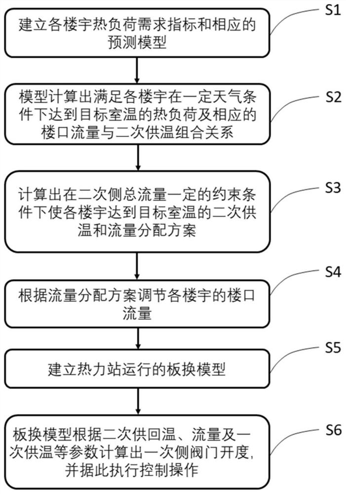
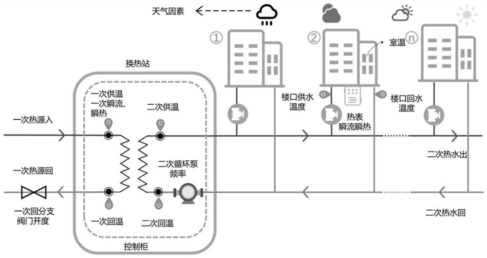
[0099] Combine figure 1 , figure 2 with image 3 The present invention is directed to a data-driven urban centralized heating system precision regulation method, including the following steps:

[0100] Step S1, establish a hot load demand indicator and corresponding prediction model of each building;

[0101] Step S2, the prediction model is used to calculate the thermal load of each building to achieve the target room temperature under certain weather conditions and the corresponding level of construction and the secondary side supply and temperature transfer combination;

[0102] Step S3, calculate the secondary side temperature and flow distribution scheme to achieve the target room temperature under certain constraints in the total flow of the secondary side;

[0103] Step S4, regulate the construction flow of each building according to the flow allocation scheme;

[0104] Step S5, establish a plate change model running by the thermal station;

[0105]Step S6, calculates the pr...

Embodiment 2

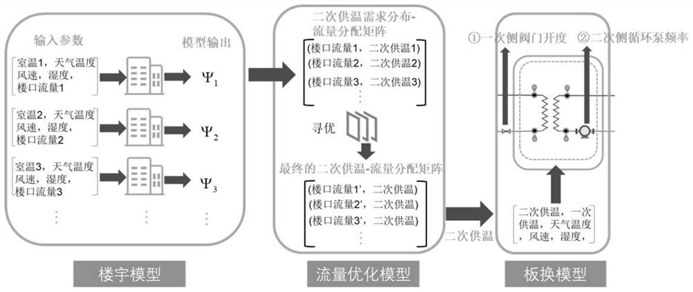
[0141] Based on the embodiment 1, the combination image 3 In this Example 2, a centralized heating system is precisely accurately controlled, including:

[0142] Model establishment module for establishing prediction model of hot load demand;

[0143] The construction flow and secondary side supply optimization module, namely image 3 The flow optimization model is used to calculate the secondary side of the secondary side to reach the building flow distribution plan to achieve the target room temperature;

[0144] The thermal station primary side valve operates the adjustment model establishment module for the secondary side of the secondary side, the secondary side flow, and the secondary side of the secondary side, the secondary side of the secondary side is supplied according to the secondary side of the second side of the current station. The model calculates the opening of a side valve, providing this parameter to the control system to perform a control operation; adjust the ...


PUM


Abstract

The present invention relates to a data-driven precise regulation and control method for urban central heating systems. The method includes the following steps: step S1, establishing heat load demand indexes and corresponding prediction models for each building; Under certain weather conditions, the heat load to reach the target room temperature and the corresponding combined relationship between the flow at the building entrance and the secondary heating supply; step S3, calculate the secondary heat supply for each building to reach the target room temperature under the constraints of a certain total flow on the secondary side supply temperature and flow distribution scheme; step S4, adjust the floor flow of each building according to the flow distribution scheme; step S5, establish a plate replacement model for the operation of the thermal station; step S6, use the plate replacement model to calculate the primary side valve opening, and according to This performs control operations. The method of the invention installs a common electric control valve at the entrance of the secondary side building, calculates the opening degree of the valve by the control system and sends an electric signal to the electric control valve, thereby saving the control cost of each building.

Description

Technical field [0001] The present invention belongs to the advanced control field of the heating system, and specifically, a method and system for optimizing the load of each building on the secondary side of the secondary side of the secondary heating system is predicted and optimized for the flow of each building. . Background technique [0002] The heating system produces high-temperature hot water in the heat source plant and drives hot water to circulate flows in a single side tube network, and transports heat to each of the thermal stations. In the thermal station, heat exchange in the secondary side, heat transfer from once The side heat exchange to the secondary side, and the secondary side is then heating to each of the secondary side tube networks. However, the current thermal station cannot accurately predict the specific load requirements of each hotter, but in order to avoid insufficient heating The problem, often takes a measure of excessive heating, resulting in p...

Claims


Application Information

Patent Timeline
Patent Type & Authority Patents(China)
IPC IPC(8): F24D19/10G06F30/13G06F119/08
CPCF24D19/1015G06F30/13G06F2119/08
Inventor 钟崴封恩程林小杰黄伟王丽腾
Owner ZHEJIANG UNIV
Why Eureka
Try Eureka