
Vehicle trajectory extraction method and device based on distributed optical fiber sensing system

A technology of distributed optical fiber and sensing system, applied in the field of intelligent transportation, can solve the problems of large influence of environmental factors, difficult construction, and poor migration application.

Active Publication Date: 2020-08-25
SICHUAN UNIV
View PDF7 Cites 9 Cited by
  • Summary
  • Abstract
  • Description
  • Claims
  • Application Information

AI Technical Summary

Problems solved by technology

[0005] The purpose of the present invention is to overcome the shortcomings of the existing sensing technology, such as small coverage, great influence by environmental factors, high cost, and difficult construction, and at the same time overcome the shortcomings of the existing vehicle trajectory extraction technology based on distributed optical fiber sensing. Due to the disadvantages of being unable to monitor the target driving trajectory over long distances, and the migration applicability in real scenes is not strong, it provides a method based on the existing infrastructure to realize vehicle trajectory extraction through the distributed optical fiber sensing system that has been laid. device for long-distance vehicle trajectory extraction in real traffic environments

Method used


Image

  • Vehicle trajectory extraction method and device based on distributed optical fiber sensing system
  • Vehicle trajectory extraction method and device based on distributed optical fiber sensing system
  • Vehicle trajectory extraction method and device based on distributed optical fiber sensing system

Examples


Embodiment 1

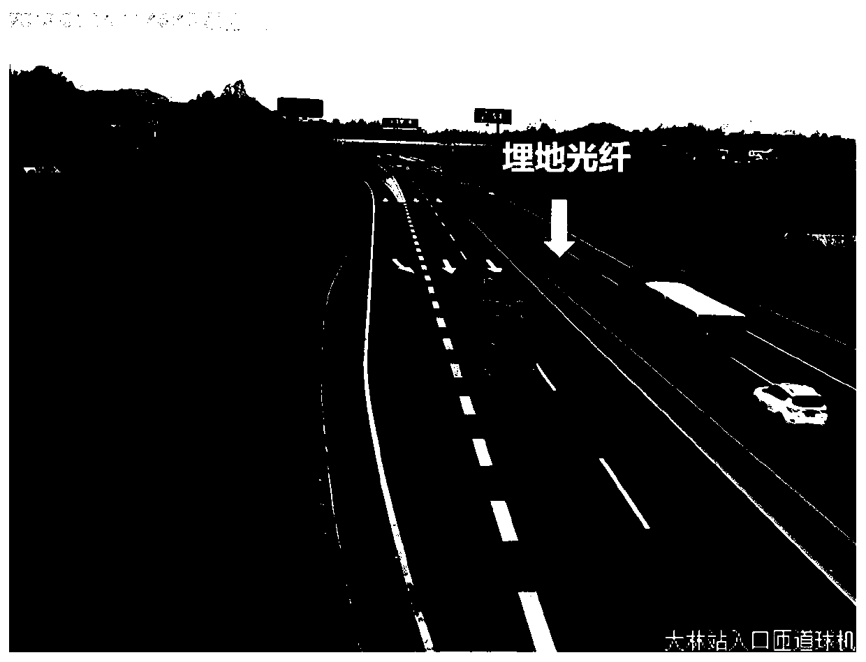
[0071] In this embodiment, a section of expressway buried with communication optical fibers is taken as the research object, and the vehicle track extraction method based on the distributed optical fiber sensing system provided by the present invention is explained in detail. like figure 1 As shown, the communication optical fiber is buried underground in the green belt in the middle of the lanes on both sides of the expressway.

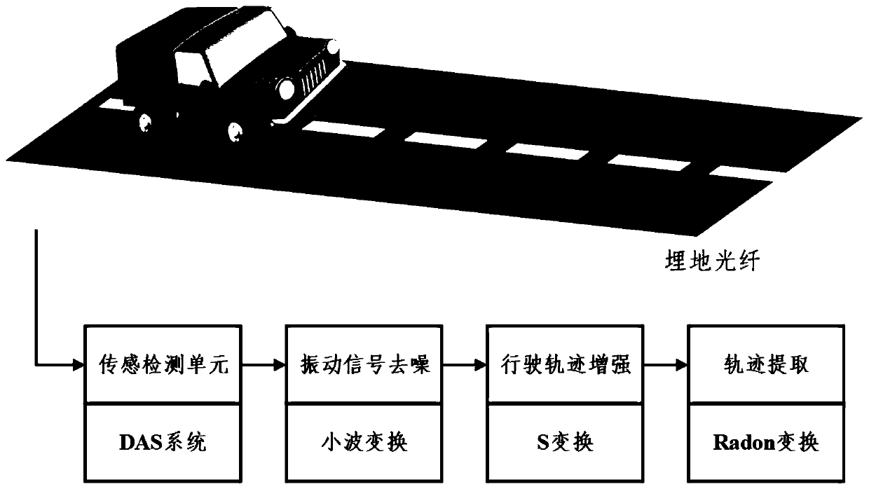
[0072] The vehicle trajectory extraction method based on the distributed optical fiber sensing system provided by this embodiment is as follows: figure 2 shown, including the following steps:

[0073] S1 uses a distributed optical fiber sensing system to measure the vibration signal generated by the vehicle's driving section in real time through optical fiber.

[0074] In this embodiment, the idle communication fiber core in the communication optical fiber laid underground in the highway is used as the optical fiber to be tested for monitoring. Th...

Embodiment 2

[0151] This embodiment provides a vehicle trajectory extraction device based on a distributed optical fiber sensing system, such as Figure 9 shown, which includes:

[0152] Distributed optical fiber sensing system for real-time measurement of vibration signals generated by vehicles on road sections through optical fibers;

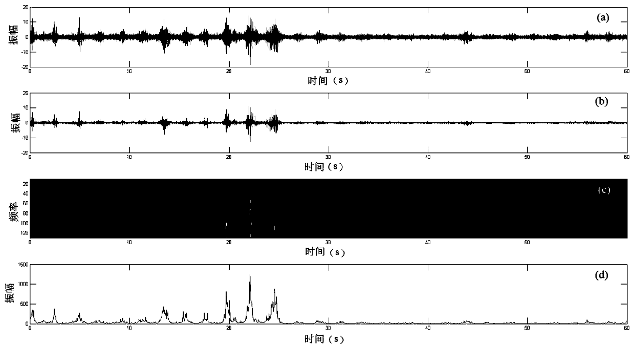
[0153] The denoising module is used to perform denoising processing on the measured vibration signal by wavelet transform;

[0154] The signal enhancement module is used to perform signal enhancement processing on the denoised vibration signal by using the S transform to obtain the space-time two-dimensional vibration energy response caused by the vehicle running;

[0155] The vehicle track extraction module is used to separate the obtained space-time two-dimensional vibration energy response signal by Radon transform to obtain the vehicle track and the vehicle speed.

[0156] The above-mentioned denoising module, signal enhancement module, and vehicle t...


PUM


Abstract

The invention discloses a vehicle trajectory extraction method and device based on a distributed optical fiber sensing system. The method comprises the following steps: firstly, measuring a vibrationsignal generated by a vehicle driving road section by a distributed optical fiber sensing system through optical fibers laid along a road; performing wavelet transform on the measured vibration signal; accumulating disturbance intensity in a time domain by utilizing S transformation to achieve the purposes of enhancing the vibration signal generated by vehicle driving and suppressing noise, and finally separating and extracting the vibration signal of the vehicle by utilizing Radon transformation to obtain a vehicle driving track, thereby realizing extraction of the vehicle driving track in anunsupervised manner.

Description

technical field [0001] The invention belongs to the technical field of intelligent transportation and relates to vehicle track extraction, in particular to a vehicle track extraction technology based on a distributed optical fiber sensing system. Background technique [0002] With the rapid development of the transportation industry, vehicle operation status monitoring plays an increasingly important role in road planning and traffic guidance. Vehicle operation status monitoring is mainly realized through technologies such as real-time detection of traffic flow, real-time detection of vehicle speed, and vehicle intention prediction, among which trajectory extraction is an important supporting link of these detection technologies. Vehicle trajectory extraction aims to extract vehicle driving signals from complex multi-source signals acquired by specific sensors, which can assist in the analysis of road traffic conditions (such as the density of vehicles, the speed of vehicles...

Claims


Application Information

Patent Timeline
IPC IPC(8): G06K9/00
CPCG06F2218/04G06F2218/08
Inventor 王茂宁张建伟钟羽中邓霖李钟麒
Owner SICHUAN UNIV
Learn More