Eureka AIR delivers breakthrough ideas for toughest innovation challenges, trusted by R&D personnel around the world.

Multifunctional heat dissipation communication cabinet convenient to maintain

A communication cabinet and multi-functional technology, applied in the field of communication, can solve the problems of general heat dissipation, poor air flow, and inconvenient maintenance, and achieve the effect of strong heat dissipation, easy maintenance, and convenient maintenance

Inactive Publication Date: 2020-08-25
纪建德
View PDF1 Cites 2 Cited by
  • Summary
  • Abstract
  • Description
  • Claims
  • Application Information

AI Technical Summary

Problems solved by technology

When the communication cabinet is placed outdoors, it is inconvenient to maintain it due to a fault, and the components in the cabinet are in a static state, the heat dissipation capacity is average, and the air flow is poor

Method used


Image

  • Multifunctional heat dissipation communication cabinet convenient to maintain
  • Multifunctional heat dissipation communication cabinet convenient to maintain
  • Multifunctional heat dissipation communication cabinet convenient to maintain

Examples


Embodiment 1

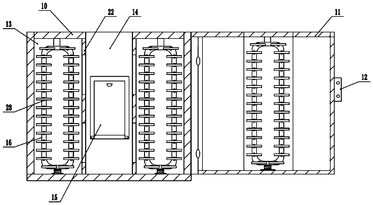
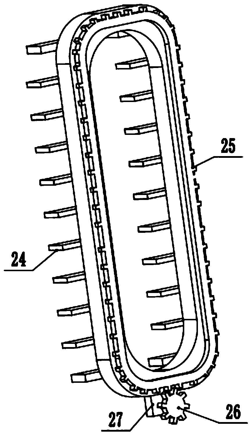
[0021] see Figure 1-4 , a kind of maintenance-friendly multifunctional heat dissipation communication cabinet, comprising a cabinet body 10, a cabinet door 11, the cabinet door 11 is hinged on the right side of the cabinet body 10, and a cabinet lock 12 is arranged on the outer middle of the cabinet door 11. The interior of the cabinet body 10 is fixedly installed with two sets of equally spaced partitions 22 from left to right, and the interior of the cabinet body 10 is divided into two groups of storage chambers 13 in the left and right cabinets and a cabinet cavity 14 in the middle through the partition boards 22 In the three areas, the inside of the storage cavity 13 in the cabinet and the inner surface of the cabinet door 11 corresponding to the cavity 14 in the cabinet are all provided with a group of annular installation tracks 16, and the top of the annular installation tracks 16 is fixed in the cabinet by connecting rods for storage. On the inner top of the cavity 13...

Embodiment 2

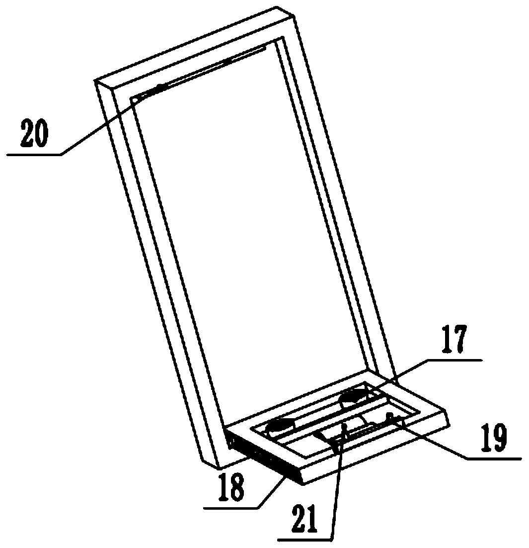
[0025] On the basis of Embodiment 1, a groove is provided on the inner side of the cavity 14 in the cabinet, and a maintenance tool box 15 is embedded in the groove. The top upper side of the groove is fixedly equipped with a latch 19, and the inner top of the maintenance tool box 15 corresponding to the latch 19 is provided with a slot 20, and by inserting the latch 19 into the slot 20, it is convenient to place the opening and closing of the groove. The inner side of the upper part of the placement groove is provided with spare wires 17 for maintenance, and the tools for maintenance are limited and stored on the outer side by a tool cover 21 . The left and right side walls of the placement slot are provided with light strips 18 for providing illumination during maintenance, and by arranging the maintenance tool box 15 inside the cabinet body 10, it is convenient for maintenance personnel to perform fast and efficient maintenance.

[0026] The working principle of the present...


PUM


Abstract

The invention relates to the technical field of communication. The invention discloses a multifunctional heat dissipation communication cabinet convenient to maintain. The cabinet comprises a cabinetbody, the cabinet door, the interior of a storage cavity in the cabinet and the inner side face, corresponding to a cavity in the cabinet, of the cabinet door are each provided with a set of annular installation rails. The tops of the annular mounting rails are fixed at the inner top of the storage cavity in the cabinet or the upper part of the inner side surface of the cabinet door through a connecting rod; a circle of rack is slidably connected to the rear side surface of each annular mounting rail; a group of servo motors are fixedly mounted on the lower surface of each annular mounting rail; the output end of the servo motor faces the position right behind the annular mounting rail and is rotationally connected with a set of gears with tops engaged with the rack through a rotating shaft, a plurality of sets of mounting rods are fixedly mounted on the front side face of the rack at equal intervals, and a component mounting plate of a rectangular structure is fixedly mounted on the front side faces of the mounting rods. The multifunctional heat dissipation communication cabinet has the advantages of being convenient and fast to maintain, high in air mobility and high in heat dissipation capacity.

Description

technical field [0001] The invention relates to the technical field of communication, in particular to a multifunctional heat dissipation communication cabinet which is convenient for maintenance. Background technique [0002] As a communication base station, the communication cabinet provides the physical working environment and security system equipment. The base station equipment, power supply equipment, temperature control equipment, transmission equipment and other supporting equipment are installed in the cabinet, or the installation space and heat exchange capacity are reserved for the above equipment. [0003] Chinese patent (notification number: CN 208159020 U, announcement date: 2018.11.27) discloses a communication cabinet, including: handle, cabinet door, hinge, base, walking wheels, drawer, power distribution device group, hand-push control Switches, control buttons, danger signal alarm devices, air outlets, rear cabinet doors, rear handles, cooling holes, light...

Claims


Application Information

Patent Timeline
IPC IPC(8): H05K7/20H05K7/18
CPCH05K7/183H05K7/186H05K7/20718
Inventor 纪建德
Owner 纪建德
Why Eureka
Eureka Blog
Learn More