Cervical vertebra anterolateral approach double-cortical fixed hook vertebral joint fusion cage

A fusion device and fixation hook technology, applied in spinal implants, medical science, prostheses, etc., can solve problems such as uncomfortable cervical spine side front surgical approach, unstable fixation, etc.

Active Publication Date: 2020-08-28
WEST CHINA HOSPITAL SICHUAN UNIV
View PDF9 Cites 2 Cited by
  • Summary
  • Abstract
  • Description
  • Claims
  • Application Information

AI Technical Summary

Problems solved by technology

[0004] The present invention provides a double-cortical fixation hook-vertebral joint fusion device for cervical lateral anterior approach, which is used to solve the problem that the ...

Method used


Image

  • Cervical vertebra anterolateral approach double-cortical fixed hook vertebral joint fusion cage
  • Cervical vertebra anterolateral approach double-cortical fixed hook vertebral joint fusion cage
  • Cervical vertebra anterolateral approach double-cortical fixed hook vertebral joint fusion cage

Examples


Embodiment 1

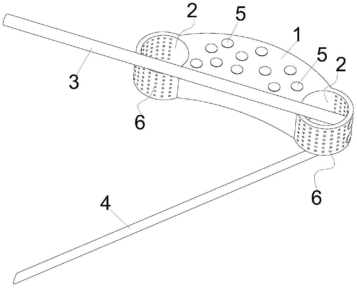
[0033] This embodiment provides a double-cortical fixation hook-vertebral arthrodesis with cervical lateral-anterior approach, which is used to implant bone graft material into the intervertebral space of the patient from the lateral-anterior approach of the cervical vertebra and support the intervertebral space.

[0034] The double cortex fixation hook vertebra arthrodesis of cervical spine lateral anterior approach comprises fusion device body 1, and this fusion device body 1 is elongated block structure, and the adopting anatomical design of this fusion device body 1, makes it It fits better with the endplates on the upper and lower sides of the intervertebral space, so that the fusion device body 1 can be better supported between the upper and lower sides of the intervertebral space, and this shape of the fusion device body 1 can be applied from It is implanted through the frontal approach of the cervical spine, so that the trachea and esophagus do not need to be pulled dur...

Embodiment 2

[0041] As a best implementation mode of this embodiment, in this embodiment, the above-mentioned fixing structure includes a first hole, a first fastener, a second hole and a second fastener, and the above-mentioned first hole is a straight hole and has a On the upper part of the bone graft cavity 2, and the first hole faces upward and forward and slopes toward the other bone graft cavity 2 side, the above-mentioned first fastener is inserted in the first hole and guided through the first hole. It is pierced and fixed sequentially on the endplate cortex, cancellous bone, and lateral cortex of a vertebra above the intervertebral space. The above-mentioned second hole is also a straight hole and opened at the lower part of the bone graft cavity 2, and the second hole faces forward. Downward and inclined towards the other side of the bone graft cavity 2, the above-mentioned second fastener is inserted into the second hole and guided through the second hole to sequentially pass thr...

Embodiment 3

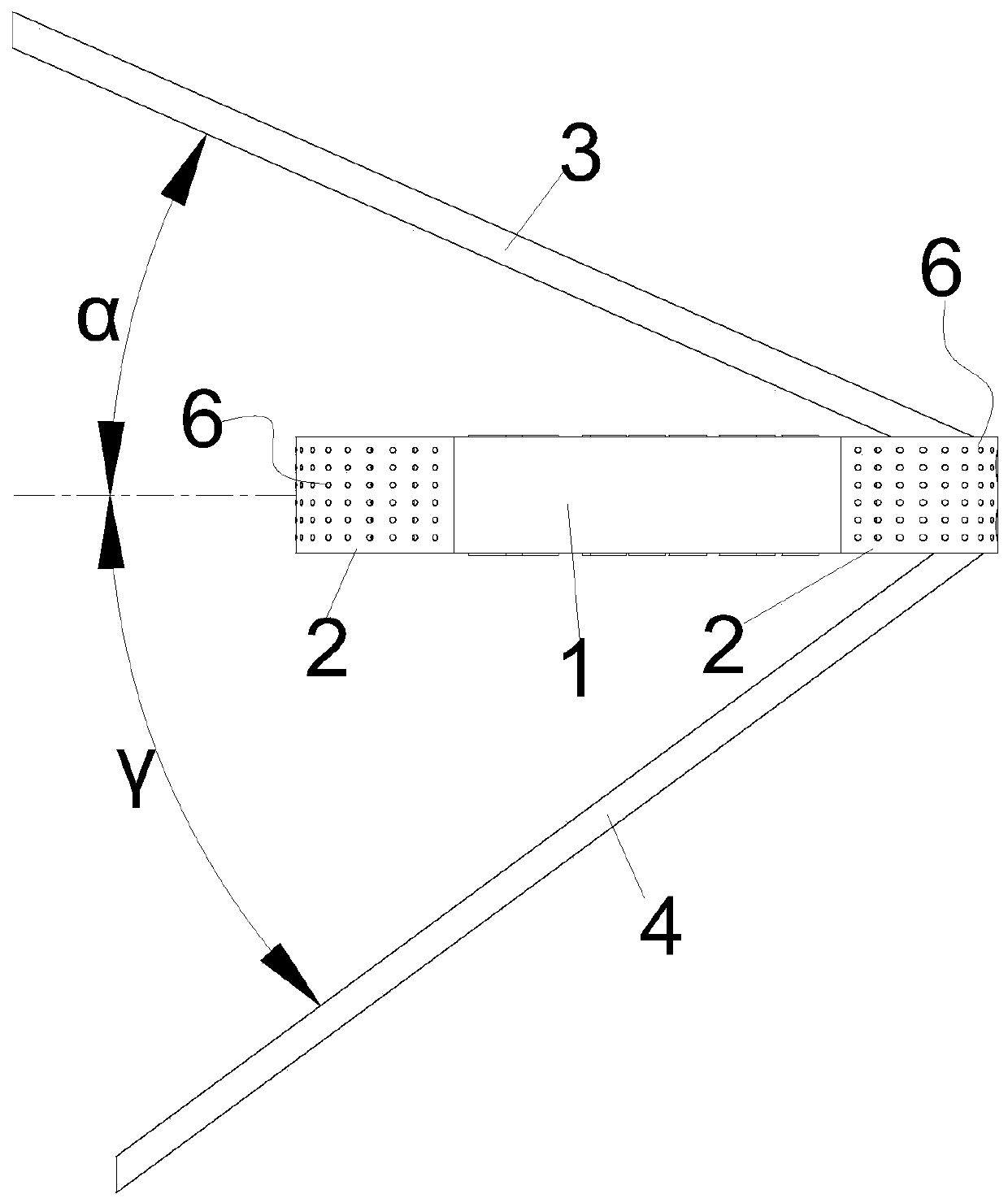
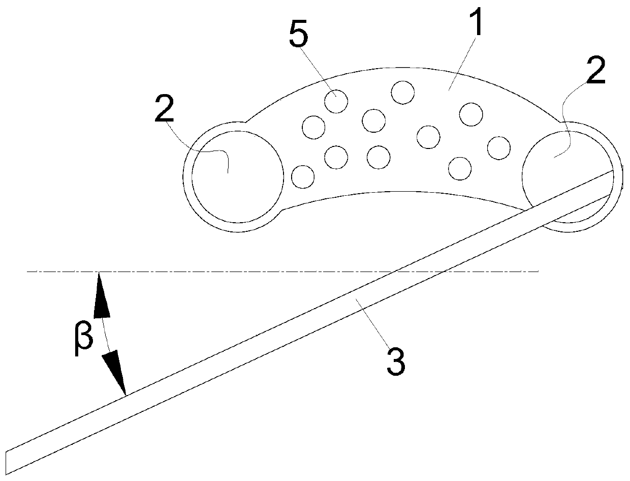
[0045] This embodiment is a best implementation mode of Embodiment 2. In this embodiment, the angle between the orthographic projection of the above-mentioned first screw 3 in the coronal plane and the horizontal line is defined as α, wherein 10°≤α≤45 °, and the angle between the orthographic projection of the first screw 3 in the transverse plane and the line connecting the left and right transverse process holes in the intervertebral space is β, 0≤β≤30°. In this way, the first screw 3 can be fixed on the endplate cortex, cancellous bone, and side cortex of a vertebra above the intervertebral space, and the first screw 3 can also perfectly avoid the carotid artery and not It will be accidentally inserted into the bone marrow located at the back of the vertebrae to ensure the safety of the double cortical fixed hook vertebral joint fusion device in the frontal approach of the cervical spine.

[0046] More preferably, the angle between the orthographic projection of the first s...


PUM


Abstract

The invention relates to a cervical vertebra anterolateral approach double-cortical fixed hook vertebral joint fusion cage, and belongs to the technical field of medical instruments. The fusion cage comprises a fusion cage body portion used for supporting a vertebra gap, the fusion cage body portion is of a long-strip-block-shaped structure, bone grafting cavities used for being filled with bone grafting materials are formed in two ends of the fusion cage body portion, the two bone grafting cavities correspond to the left portion of the vertebra gap and the right portion of the vertebra gap respectively, and a fixing structure used for being sequentially connected and fixed to a vertebral end plate cortical bone, a cancellous bone and a lateral cortical bone in a penetrating mode is arranged on a cavity wall of one of the bone grafting cavities. By means of the structure, the fusion cage can be suitable for being implanted into the vertebra gap from a cervical vertebra anterolateral approach, can be fixed in the cervical vertebra anterolateral direction through the fixing structure, and is fixed to the vertebral end plate cortical bone, the cancellous bone and the lateral corticalbone, and therefore, the fusion cage can be stably connected to the inside of the vertebra gap, and growth of the bone grafting materials is better facilitated.

Description

technical field [0001] The invention belongs to the technical field of medical devices, and in particular relates to a double-cortical fixation hook-vertebral joint fusion device with anterior cervical approach. Background technique [0002] Anterior cervical decompression and fusion has always been a classic and effective surgical method for the treatment of cervical degenerative diseases. During the operation, the trachea and esophagus need to be stretched and the annulus fibrosus and anterior longitudinal ligament of the corresponding parts need to be resected. Therefore, This operation will destroy the segmental stability of the vertebrae, and there is a risk of postoperative complications such as dysphagia. In order to solve this technical problem, some researchers proposed to implant the fusion device from the side and front of the cervical spine. When performing fusion through the side and front approach, it is a small opening in the side and front of the intervertebr...

Claims


Application Information

Patent Timeline
IPC IPC(8): A61F2/44
CPCA61F2/4455A61F2220/0008A61F2220/0016
Inventor 丁琛刘浩杨毅
Owner WEST CHINA HOSPITAL SICHUAN UNIV
Why Eureka
Try Eureka