Treatment method and device for efficiently absorbing formaldehyde
A formaldehyde absorption and treatment method technology, applied in the cleaning field, can solve the problems of high cost and expensive filter membrane, and achieve the effects of low cost, improved absorption and treatment efficiency, and easy operation
- Summary
- Abstract
- Description
- Claims
- Application Information
AI Technical Summary
Problems solved by technology
Method used
Image
Examples
Embodiment 1
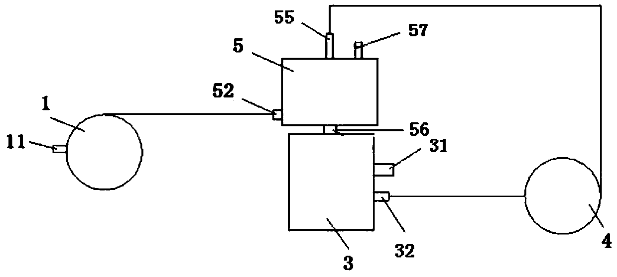
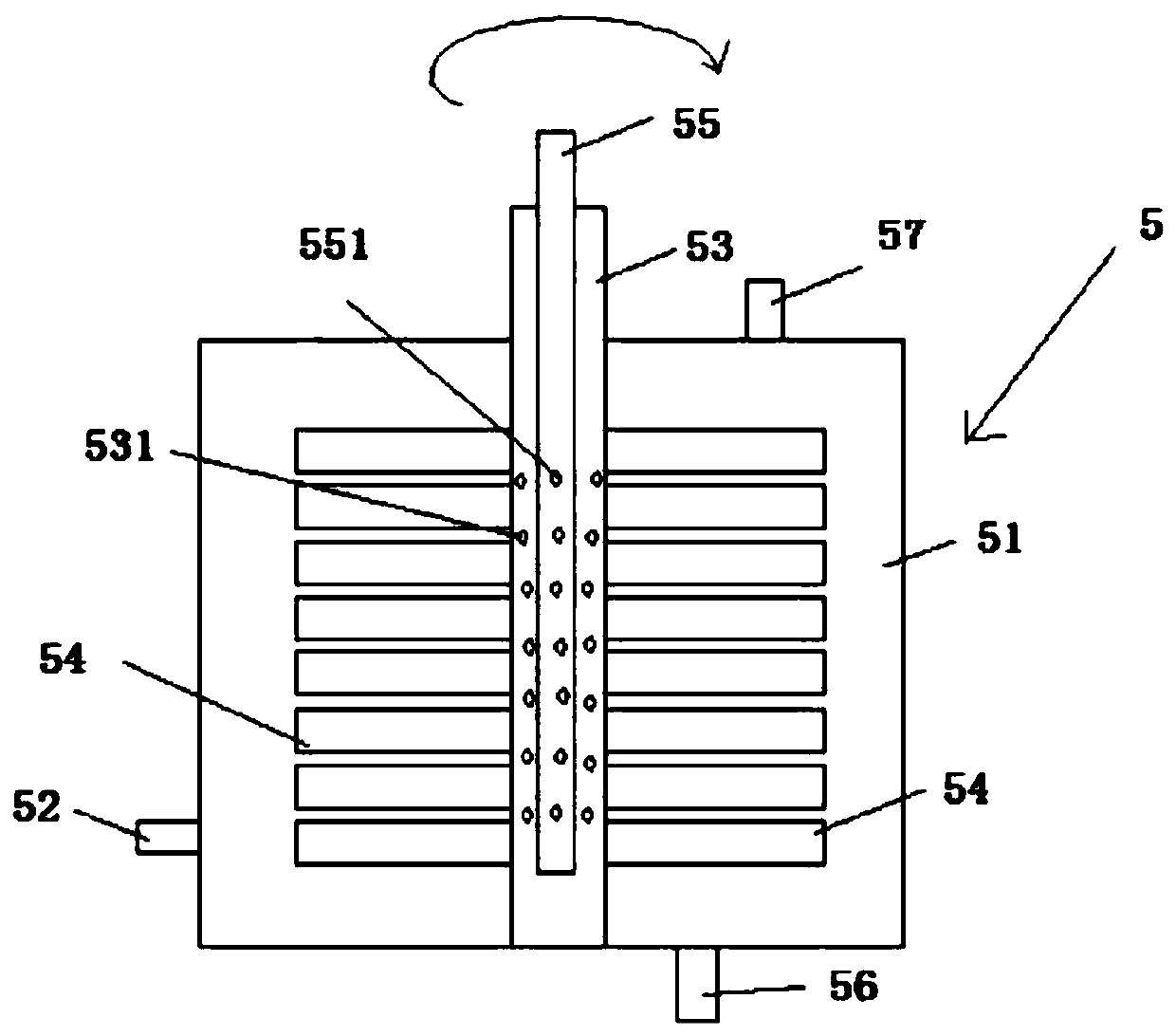
[0040] Such as figure 2 As shown, a treatment device for efficiently absorbing formaldehyde includes an air pump 1, a multi-layer rotary disc mixer 5, a liquid storage tank 3, and a circulation pump 4. The multi-layer rotary disc mixer 5 (see image 3 ) includes a sealed case 51, an air inlet 52 is provided on one side of the outer wall of the sealed case 51 near the bottom, an air outlet 57 is provided above the sealed case 51, a liquid outlet 56 is provided below the sealed case 51, and the sealed case 51 A cylindrical rotating shaft 53 is fixedly inserted in the center, and rotating turntables 54 are arranged at fixed intervals on the rotating shaft 53, and the distance between adjacent rotating turntables is 0.1-0.8mm; the upper surface of the rotating turntable 54 has multiple grooves or Ribs, several first spray holes 531 with a diameter of 0.5-2 mm are arranged on the rotating shaft 53 at the interval between adjacent rotating turntables 54, and the center of the rotat...
Embodiment 2
[0043] Such as Figure 4 As shown, a treatment device for efficiently absorbing formaldehyde includes an air pump 1, a microreactor 6, a gas-liquid separator 7, a liquid storage tank 3, a circulation pump 4, an air inlet 61 and an inlet of the microreactor 6. The liquid port 62 is connected with the suction pump 1 and the circulation pump 4 respectively, and the liquid discharge port 32 of the liquid storage tank 3 is connected with the inlet of the circulation pump; the liquid outlet 63 of the microreactor 6 is connected with the gas-liquid separator 7, and the gas-liquid is mixed. After entering the gas-liquid separator 7 from the liquid inlet port 71, the gas-liquid separation is realized, the clean air is discharged from the exhaust port 72 of the gas-liquid separator 7, and the liquid enters the liquid storage tank 3 from the liquid discharge port 73 of the gas-liquid separator 7 , the specific structure of the microreactor 6 is as Figure 5 , as shown in 6.
[0044] Th...
PUM
 Abstract
Description
Claims
Application Information
 - R&D
- Intellectual Property
- Life Sciences
- Materials
- Tech Scout
- Unparalleled Data Quality
- Higher Quality Content
- 60% Fewer Hallucinations
Browse by: Latest US Patents, China's latest patents, Technical Efficacy Thesaurus, Application Domain, Technology Topic, Popular Technical Reports.
© 2025 PatSnap. All rights reserved.Legal|Privacy policy|Modern Slavery Act Transparency Statement|Sitemap|About US| Contact US: help@patsnap.com


