
Temperature-controllable magnetic stirrer and working method thereof

A magnetic stirrer and temperature controller technology, applied in chemical instruments and methods, mixer accessories, dissolution, etc., can solve the problems of affecting the experimental effect, easy to move, affecting the magnetic induction effect, etc., to improve the dissolution efficiency and structural design Reasonable and solve the effect that is not easy to take out

Pending Publication Date: 2020-08-28
SUZHOU BEIKAI BIOCHEM EQUIP
View PDF0 Cites 3 Cited by
  • Summary
  • Abstract
  • Description
  • Claims
  • Application Information

AI Technical Summary

Problems solved by technology

[0002] The magnetic stirrer uses the principle of magnetic field and vortex to put the liquid into the container, and put the stirrer into the liquid at the same time. When the base generates a magnetic field, it drives the stirrer to move in a circular motion to achieve the purpose of stirring the liquid. It is suitable for viscous It is not a large liquid or solid-liquid mixture; during use, the magnetic stirring bar rotates, causing the solution in the stirring cup to vortex, which promotes the dissolution of the solute and the acceleration of the reaction; however, it is found in practical applications that the stirring cup is affected by the rotation of the stirring bar Influence, easy to move, after the stirring cup deviates from the area directly above the strong magnet, it will affect the effect of magnetic induction, and the stirring rotor will rotate irregularly or even stop rotating, which will affect the experimental effect

Method used


Image

  • Temperature-controllable magnetic stirrer and working method thereof
  • Temperature-controllable magnetic stirrer and working method thereof
  • Temperature-controllable magnetic stirrer and working method thereof

Examples


Embodiment Construction

[0018] The present invention will be further explained below in conjunction with the accompanying drawings and specific embodiments.

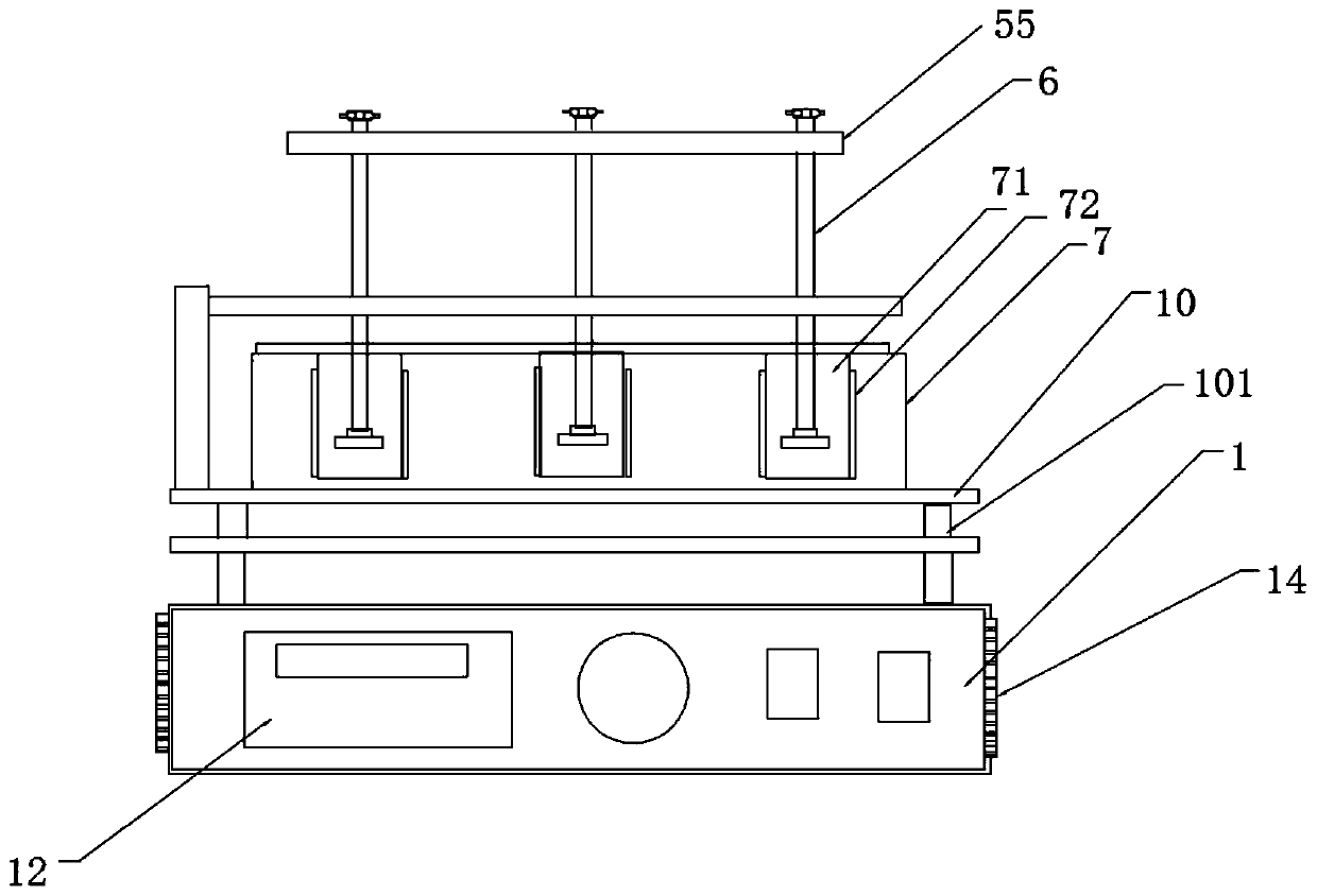
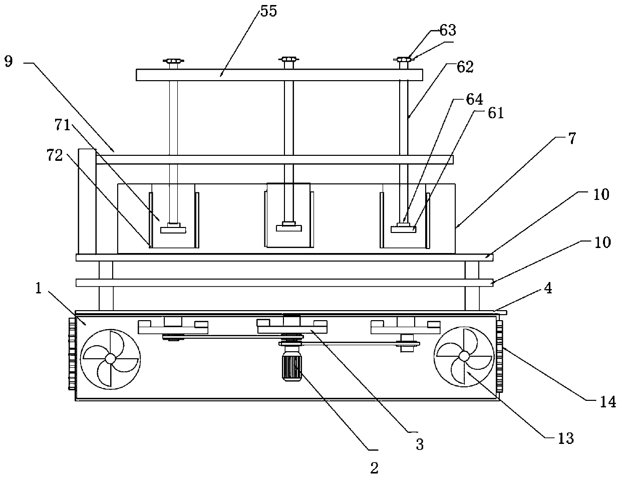
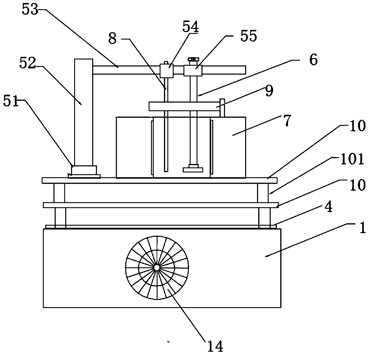
[0019] like Figure 1-4 The temperature-controllable magnetic stirrer shown includes a base 1, a motor 2, a magnet support 3, a stage 4, a support assembly 5, a stirring body 6, a stainless steel pot body 7 and a temperature sensor 8, and the base 1 is equipped with Motor 2 and magnet support 3 are arranged, and described magnet support 3 comprises magnet support one 31, magnet support two 32 and magnet support three 33, and above-mentioned 3 magnet supports are respectively installed in base 1 by drive shaft, and magnet support two 32 The output shaft of drive shaft and motor 2 is connected by coupling, and the output shaft of described motor 2 is provided with 2 drive wheels, and the drive shafts of magnet support one 31 and magnet support three 33 are all provided with driven wheels, driving wheels and the driven wheel are driven by belts; ...


PUM


Abstract

The invention discloses a temperature-controllable magnetic stirrer which comprises a base, a motor, a magnet bracket, an objective table, a bracket assembly, a stirring body, a stainless steel pot body and a temperature sensor; a motor and a magnet bracket are arranged in the base; the objective table is arranged on the base; the stainless steel pot body is arranged on the objective table, a plurality of reaction cavities are formed in the stainless steel pot body, heating wires are arranged on the outer walls of the reaction cavities, a sliding rail is arranged on the base, the support assembly is slidably arranged on the sliding rail, a plurality of stirring bodies and temperature sensors are arranged on the support assembly, and a temperature controller, a rotating speed adjusting knob, a power switch and a heating switch are arranged on the front side of the base; a plurality of stirring cups containing liquid can be used for simultaneously heating the liquid in the stirring process; the stirrer is arranged in the reaction cavity, so that the stirring cup is not liable to moving in the rotating process of the stirrer, and the stirring body located above the stirring cup can beconveniently taken out of the stirring cup after stirring is finished, and thereby the problem that the stirrer is not prone to being taken out of viscous liquid is solved.

Description

technical field [0001] The invention relates to the technical field of stirring, in particular to a temperature-controllable magnetic stirrer and a working method thereof. Background technique [0002] The magnetic stirrer uses the principle of magnetic field and vortex to put the liquid into the container, and put the stirrer into the liquid at the same time. When the base generates a magnetic field, it drives the stirrer to move in a circular motion to achieve the purpose of stirring the liquid. It is suitable for viscous It is not a large liquid or solid-liquid mixture; during use, the magnetic stirring bar rotates, causing the solution in the stirring cup to vortex, which promotes the dissolution of the solute and the acceleration of the reaction; however, it is found in practical applications that the stirring cup is affected by the rotation of the stirring bar Influence, easy to move, after the stirring cup deviates from the area directly above the strong magnet, the e...

Claims


Application Information

Patent Timeline
IPC IPC(8): B01F13/10B01F13/08B01F15/00B01F15/06
CPCB01F33/453B01F33/813B01F35/2215B01F35/413B01F35/43B01F35/92B01F2035/99B01F2101/23
Inventor 何钰婧
Owner SUZHOU BEIKAI BIOCHEM EQUIP
Learn More