High-strength unsaturated polyester resin cloth inserted pipe production processing line
A polyester resin and unsaturated technology, applied in the field of cloth pipe production, can solve the problems of difficult control of production environment humidity, affecting work efficiency, low production efficiency, etc., to facilitate continuous operation, improve production quality, and reduce labor costs Effect
- Summary
- Abstract
- Description
- Claims
- Application Information
AI Technical Summary
Problems solved by technology
Method used
Image

Examples
Embodiment Construction
[0039] In order to make the technical means, creative features, goals and effects achieved by the present invention easy to understand, the present invention will be further elaborated below in conjunction with illustrations and specific embodiments.
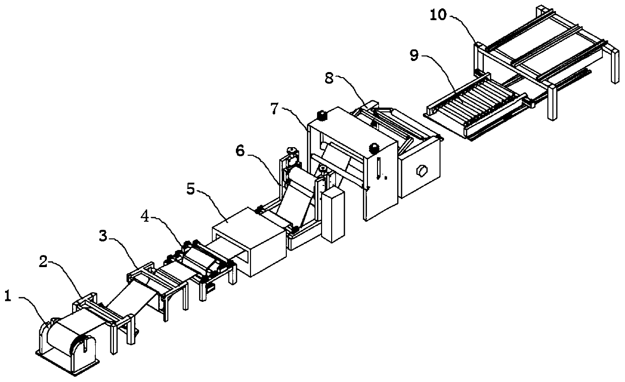
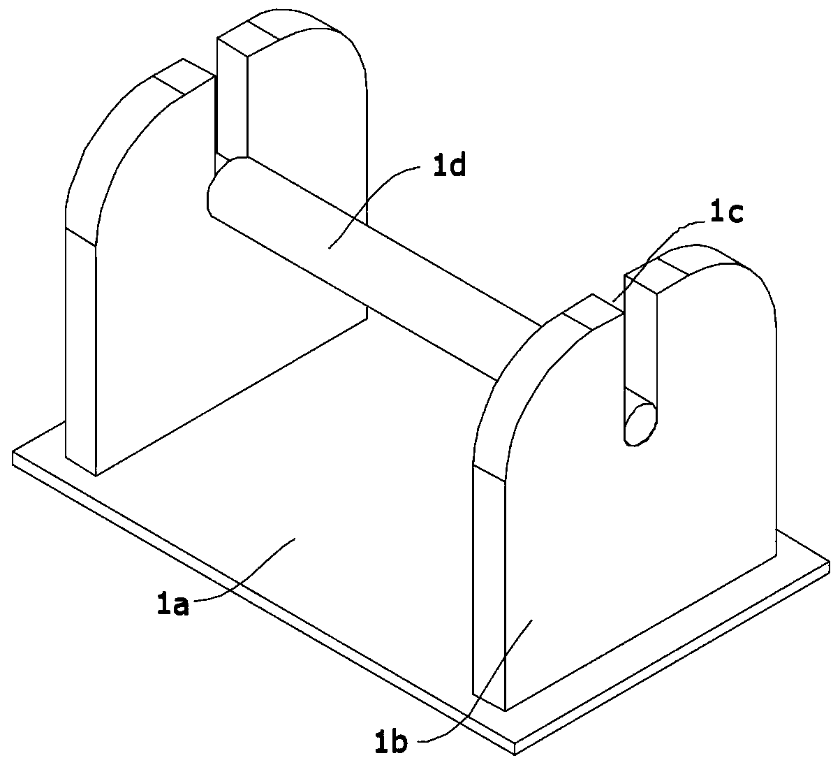
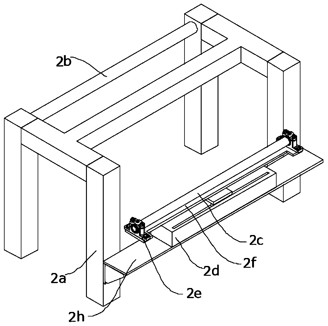
[0040] combine figure 1 , Figure 6 , Figure 7and Figure 9 As shown, the present invention proposes a high-strength unsaturated polyester resin cloth pipe production and processing line, the processing line includes a cloth rack 1, a deviation correction mechanism 2, a first tensioning mechanism 3, a second tensioning Mechanism 4, oven 5, dipping mechanism 6, cloth storage mechanism 7, rotary winding mechanism 8, transfer rack 9 and drying mechanism 10; the rotary winding mechanism 8 includes two symmetrical rotating fixed brackets 8a, two A winding roller assembly 8b is rotatably arranged between the two rotating fixed brackets 8a, and the winding roller assembly 8b includes a symmetrical first connecting frame 8b1 and a s...
PUM
 Abstract
Description
Claims
Application Information
PatSnap Eureka turns technology decisions into work you can execute. Powered by our Innovation Knowledge Graph, it runs expert workflows across engineering, life sciences, materials and intellectual property. Get your review-ready output in minutes.


