
Printing display-oriented printing height control system and method

A printing height and control system technology, applied in the direction of feedback control, printing, typewriter, etc., can solve problems such as the decline of yield rate, nozzle nozzle damage, panel substrate damage, lack of automatic measurement and positioning solutions, etc., to reduce errors , the effect of improving the degree of automation

Active Publication Date: 2020-08-28
武汉国创科光电装备有限公司
View PDF4 Cites 0 Cited by
  • Summary
  • Abstract
  • Description
  • Claims
  • Application Information

AI Technical Summary

Problems solved by technology

In terms of process requirements, it is necessary to control the absolute distance from the nozzle surface of the nozzle to the panel substrate and adjust it accurately. When the panel substrate is mass-produced, it is necessary to ensure high printing consistency and high repeatability. If the printing height exceeds the allowable error, it will increase the ink drop point The impact of deviation, resulting in a decline in yield
[0003] There are two traditional printing height positioning methods: the striker detection positioning method and the non-contact measurement combined with the input substrate thickness positioning method. Among them, the striker detection method, the striker, the nozzle of the nozzle and the panel substrate will contact each other, and the nozzle of the nozzle and the panel substrate will have contact. Possibility of damage; laser displacement sensors are widely used in non-contact measurement. Although non-destructive measurement is solved, the thickness of the panel substrate needs to be known, which cannot meet the needs of automation and safety protection.
Both methods lack solutions for automatic measurement and positioning. Correspondingly, there is an urgent need to propose more appropriate solutions in this field to meet the current increasing technological requirements.

Method used


Image

  • Printing display-oriented printing height control system and method
  • Printing display-oriented printing height control system and method
  • Printing display-oriented printing height control system and method

Examples


Embodiment Construction

[0059] In order to make the object, technical solution and advantages of the present invention clearer, the present invention will be further described in detail below in conjunction with the accompanying drawings and embodiments. It should be understood that the specific embodiments described here are only used to explain the present invention, not to limit the present invention. In addition, the technical features involved in the various embodiments of the present invention described below can be combined with each other as long as they do not constitute a conflict with each other.

[0060] It should be noted that the term "first\second" in the present invention is only used to distinguish similar objects, and does not represent a specific ordering of objects. It is understandable that "first\second" can be used interchangeably when permitted in a particular order or sequence. It should be understood that the terms "first\second" are interchangeable under appropriate circum...


PUM


Abstract

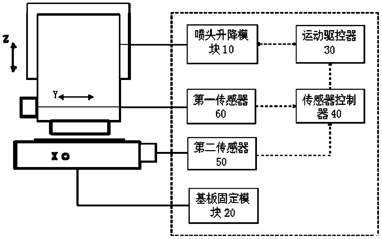
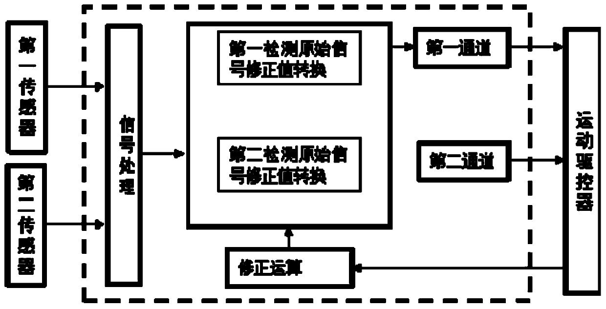
The invention provides a printing display-oriented printing height control system and method. The printing display-oriented printing height control system comprises a spray head lifting module, a substrate fixing module, a first sensor, a second sensor, a sensor controller and a motion driving controller; the spray head lifting module comprises a spray head, a spray head clamping device and a lifting mechanism; the substrate fixing module is arranged below the spray head lifting module and comprises an adsorption platform; the first sensor and the second sensor are used for detecting the real-time distance between a nozzle and a substrate and generating a first detection original signal and a second detection original signal; the sensor controller is used for acquiring the first detectionoriginal signal and the second detection original signal and sending the first detection original signal and the second detection original signal to the motion driving controller through signal processing and correction operation; and the motion driving controller is used for carrying out full-closed-loop control and driving on the lifting mechanism. According to the printing display-oriented printing height control system and method, the printing height control system and the two sensors are arranged in a combined mode, measured values of the multiple detected objects are corrected, the height or position relation is established, and non-contact self-adaptive printing height positioning control can be better achieved.

Description

technical field [0001] The invention belongs to the technical field related to inkjet printing, and more specifically relates to a printing height control system and method for printing display. Background technique [0002] At present, the new inkjet printing technology is widely used in the industrial manufacturing industry. In particular, with the OLED panel manufacturing cost reduction and efficiency requirements, compared with the evaporation process, the OLED panel manufacturing process using inkjet printing technology is to reduce production costs and increase A feasible method of efficiency, while the inkjet printing process is becoming more and more perfect, it is necessary to solve the problems of automation, precision control, and reliability of the inkjet printing system. Among them, due to the special structure of the piezoelectric nozzle, the nozzle surface of the nozzle is fragile, easy to be polluted and blocked, and the printing height detection and precise ...

Claims


Application Information

Patent Timeline
IPC IPC(8): B41J25/304B41J2/01B41J3/407B41J25/00G05D3/12
CPCB41J2/01B41J3/407B41J25/00B41J25/304G05D3/12
Inventor 尹周平陈建魁潘浩雷春耀高俊伟
Owner 武汉国创科光电装备有限公司
Learn More