Environment-friendly floating island for artificial ecological lake and using method

An artificial ecological and environmental protection technology, applied in chemical instruments and methods, botanical equipment and methods, applications, etc., can solve problems such as ecological impact, affecting the beauty of lakes and floating islands, and achieve the effect of avoiding rotation.

Inactive Publication Date: 2020-08-28
绍兴市晟途环保科技有限公司
View PDF0 Cites 4 Cited by
  • Summary
  • Abstract
  • Description
  • Claims
  • Application Information

AI Technical Summary

Problems solved by technology

[0002] Due to the lack of natural lakes in many places, artificial ecological lakes will be built in order to make a beautiful plan for the environment. During the maintenance of the ecological lake, for the ecological development and beautification of the ecological lake, floating islands will be built in t

Method used


Image

  • Environment-friendly floating island for artificial ecological lake and using method
  • Environment-friendly floating island for artificial ecological lake and using method
  • Environment-friendly floating island for artificial ecological lake and using method

Examples


Example Embodiment

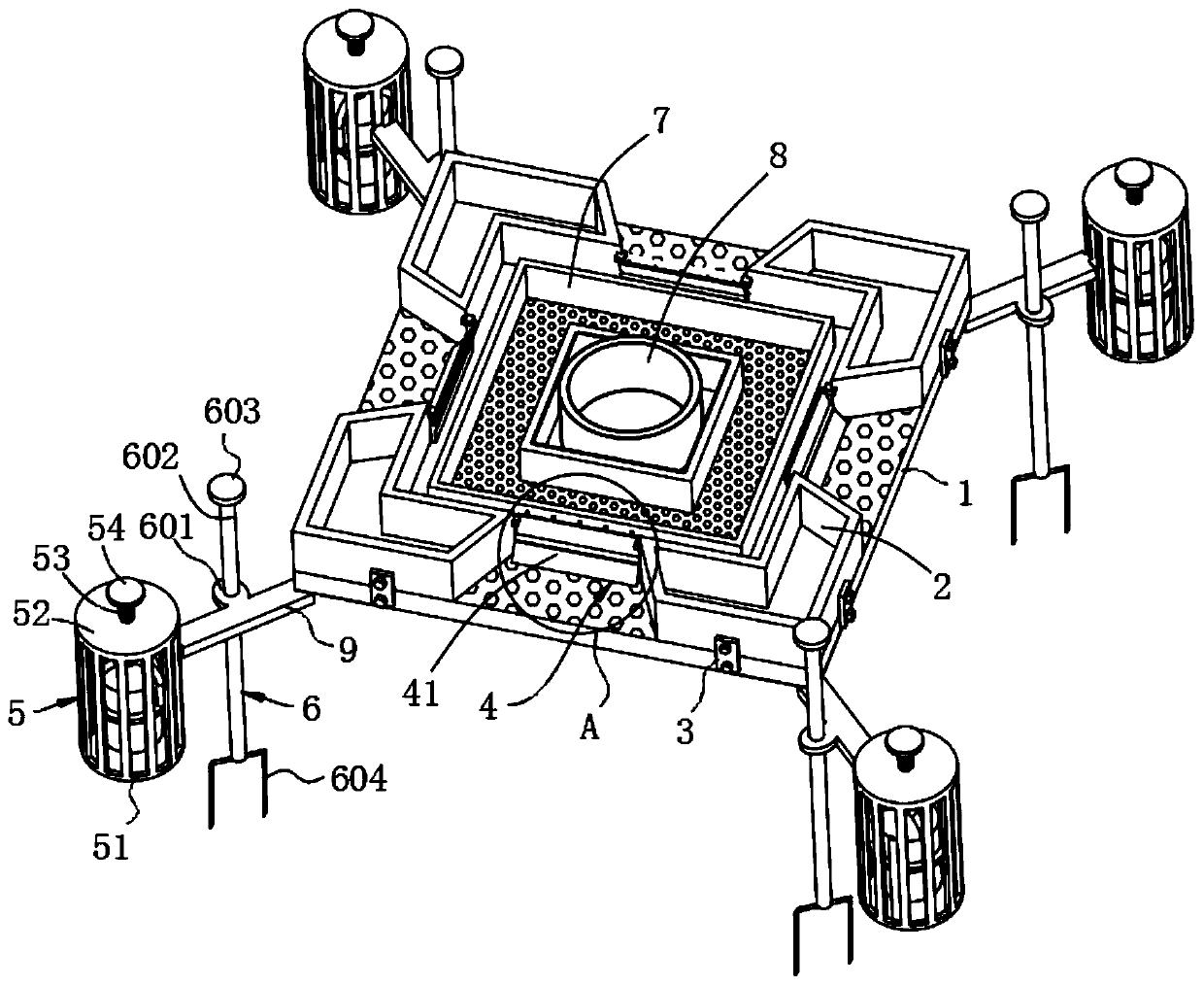
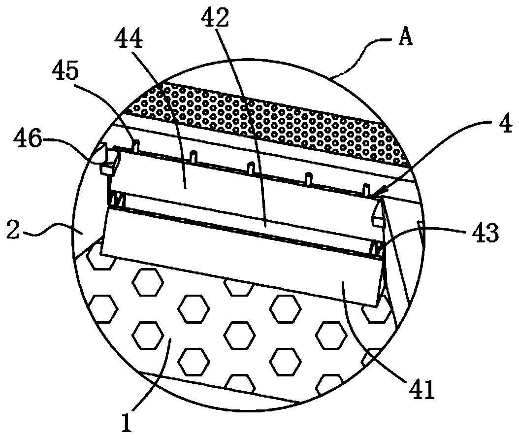
[0044] Example 1: Please refer to Figure 1-5 , Environmental protection floating island for artificial ecological lake, including floating board 1, planting tank 1, floating garbage collection unit 4 and floating unit 5;

[0045] The floating plate 1 is rectangular and evenly provided with meshes. The four corners of the upper surface of the floating plate 1 are respectively provided with an L-shaped structure of the planting trough 1-2, and the two right-angled sides of the planting trough 1-2 are flat with the right-angled sides of the floating plate 1. The outer surface of the right-angle side of the implant tank 1 is connected to one end of the connecting strip 3 by bolts, the other end of the connecting strip 3 is connected to the outer surface of the right-angle side of the floating plate 1 by bolts, and the two ends of the four implant tanks 1 It is arranged obliquely and forms an isosceles trapezoid gap in the middle of the four sides of the floating board 1, and the sho...

Example Embodiment

[0066] Example 2: Please refer to Image 6 The position fixing unit 6 includes a turntable 611, a connecting block 612, a connecting rope 613, a spring 614, a connecting rope 615, a bottom ring 616, and a ground pin 617. The turntable 611 is rotatably connected to the bottom center of the floating plate 1, and the turntable 611 There are no less than four connecting blocks 612 at equal angles on the side of the connecting block 612. A connecting rope 613 is tied in the connecting hole of the connecting block 612. The other end of the connecting rope 613 is connected to one end of the spring 614, and the other end of the spring 614 is connected to One end of the second rope 615 and the other end of the second connecting rope 615 are connected to the bottom ring 616, and a ground pin 617 is inserted into a pin hole of the bottom ring 616.

[0067] The bottom ring 616 is fixed to the bottom of the lake through a ground pin 617, the turntable 611 is rotatably connected to the bottom o...

Example Embodiment

[0068] Example 3: Please refer to Figure 7 with 8 The position fixing unit 6 includes a pull rope 621, a fixing frame 622, a second ground pin 623, a mounting plate 624, a bobbin 625 and a second torsion spring 626. The bottoms of the four support rods 9 are respectively connected to one end of the pull rope 621 to pull The other end of the rope 621 is fixedly wound on the bobbin 625, the two ends of the bobbin 625 are rotatably connected to the fixing frame 622, the two ends of the bobbin 625 are sleeved with torsion spring two 626, one end of the torsion spring two 626 It is fixed on the bobbin 625, and the other end of the second torsion spring 626 is fixed on the fixing frame 622. A mounting plate 624 is fixed on the side of the fixing frame 622, and a second ground pin 623 is inserted into the pin hole of the mounting plate 624.

[0069] The mounting plate 624 is fixed on the bottom of the lake through the second ground pin 623 inserted in the pin hole of the mounting plate ...


PUM


Abstract

The invention discloses an environment-friendly floating island for an artificial ecological lake and a using method. The environment-friendly floating island comprises a floating plate, first planting groove bodies, a floating garbage collecting unit and a floating unit. The floating plate is rectangular and is uniformly provided with meshes; the first planting groove bodies of L-shaped structures are arranged at the four corners of the upper surface of the floating plate correspondingly; the two right-angle sides of each first planting groove body are flush with the right-angle edges of thefloating plate; the outer side surface of the right-angle side of each first planting groove body is connected with one end of a connecting strip through a bolt; the other end of each connecting stripis connected with the outer side face of the right-angle side of the floating plate through bolts; the two ends of the four first planting groove bodies are obliquely arranged, isosceles-trapezoid-shaped notches are formed in the middles of the four side faces of the floating plate; the short sides of the notches are located inside, the long sides of the notches face outwards, and the floating garbage collecting unit is installed on the short side of each notch. According to the environment-friendly floating island for the artificial ecological lake and the using method, garbage attached to the periphery of the floating island can be collected through stormy waves, ecology is protected, and the lake surface and the floating island can be kept attractive.

Description

technical field [0001] The invention relates to the technical field of environment-friendly floating islands, in particular to environment-friendly floating islands for artificial ecological lakes and their usage methods. Background technique [0002] Due to the lack of natural lakes in many places, artificial ecological lakes will be built in order to make a beautiful plan for the environment. During the maintenance of the ecological lake, for the ecological development and beautification of the ecological lake, floating islands will be built in the ecological lake to maintain the floating island However, since there are often floating garbage on the lake, these garbage are easily attached to the surroundings of the floating island, which has a great impact on the ecology, and also affects the beauty of the lake and the floating island. Contents of the invention [0003] The technical problem to be solved by the present invention is to overcome the existing defects, provi...

Claims


Application Information

Patent Timeline
IPC IPC(8): C02F3/32A01G31/02
CPCA01G31/02C02F3/32C02F2103/007Y02P60/21
Inventor 赵彦
Owner 绍兴市晟途环保科技有限公司
Why Eureka
Try Eureka