
Distributed hashrate center waste heat recovery cooling and heating unit

A waste heat recovery and distributed technology, used in mechanical equipment, non-variable-capacity pumps, machines/engines, etc., can solve problems such as troublesome removal of the protective cover, vibration caused by the operation of the unit, damage to the protective cover, etc. Or damaged, easy to clean or replace, disassembly and assembly to save time and effort

Inactive Publication Date: 2020-08-28
江西锋铄新能源科技有限公司
View PDF7 Cites 0 Cited by
  • Summary
  • Abstract
  • Description
  • Claims
  • Application Information

AI Technical Summary

Problems solved by technology

[0003] The existing waste heat recovery cooling and heating units have the following shortcomings. First, the unit is placed outdoors for a long time, and the protective cover is easily affected by extreme weather, such as heavy snow or hail, which will cause damage to the protective cover. However, the existing protective cover needs special It is very troublesome to disassemble with tools. Secondly, during long-term use, the fan and its fan blades of the unit need to be fixed regularly. However, in the prior art, the fan blades are often directly fixed on the fan shaft, so when cleaning , the fan blades will often cause occlusion, making the cleaning work incomplete, and the unit will vibrate during operation. Long-term vibration will easily cause damage to the unit. In typhoon weather, there is a risk of the unit being blown, which increases the safety response. In view of the deficiencies in the prior art, the present invention discloses a cooling and heating unit with waste heat recovery in a distributed computing power center to solve the above problems

Method used


Image

  • Distributed hashrate center waste heat recovery cooling and heating unit
  • Distributed hashrate center waste heat recovery cooling and heating unit
  • Distributed hashrate center waste heat recovery cooling and heating unit

Examples


Embodiment Construction

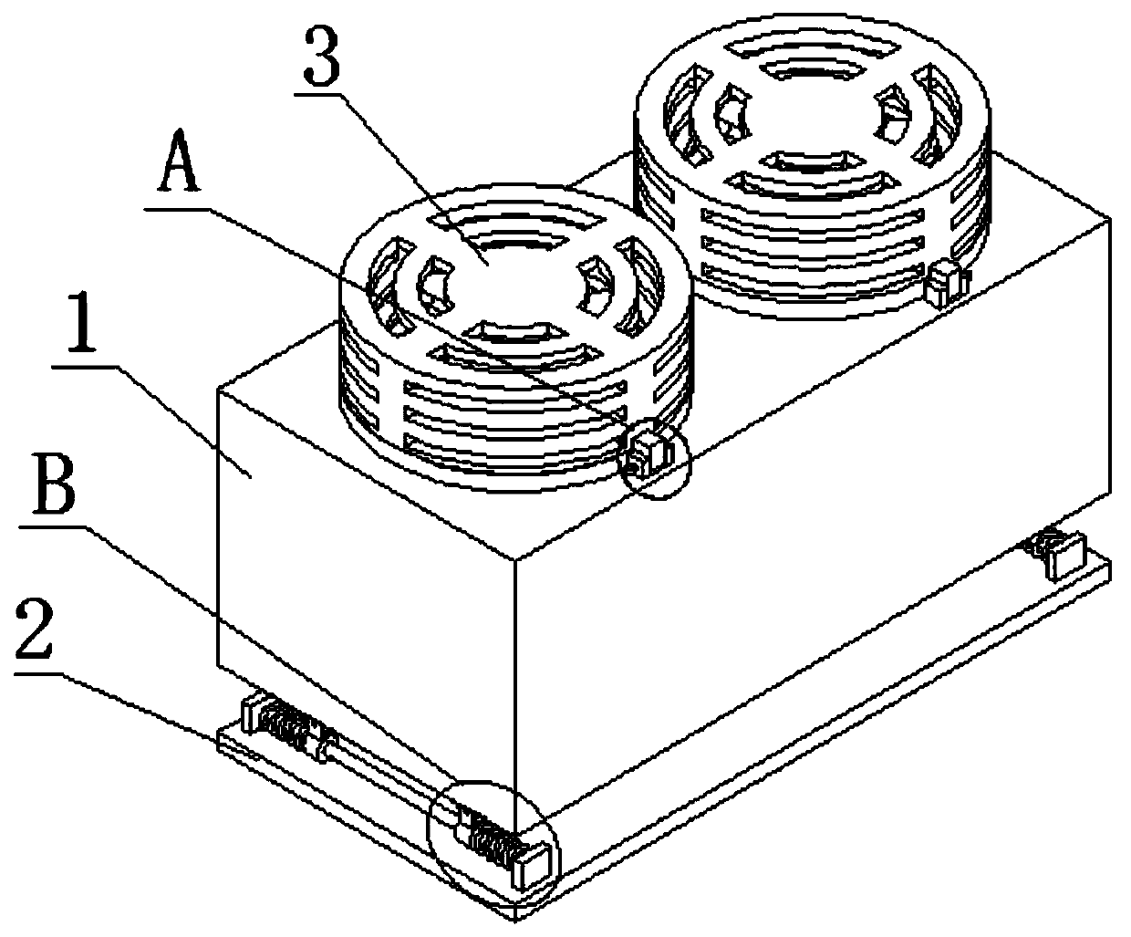
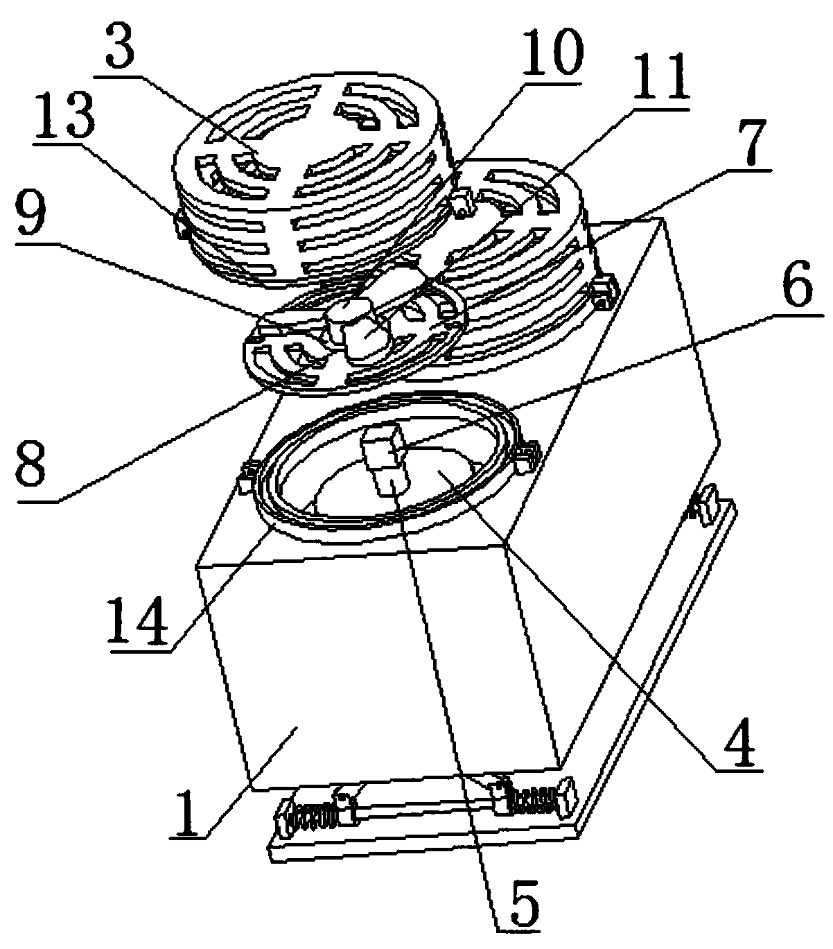
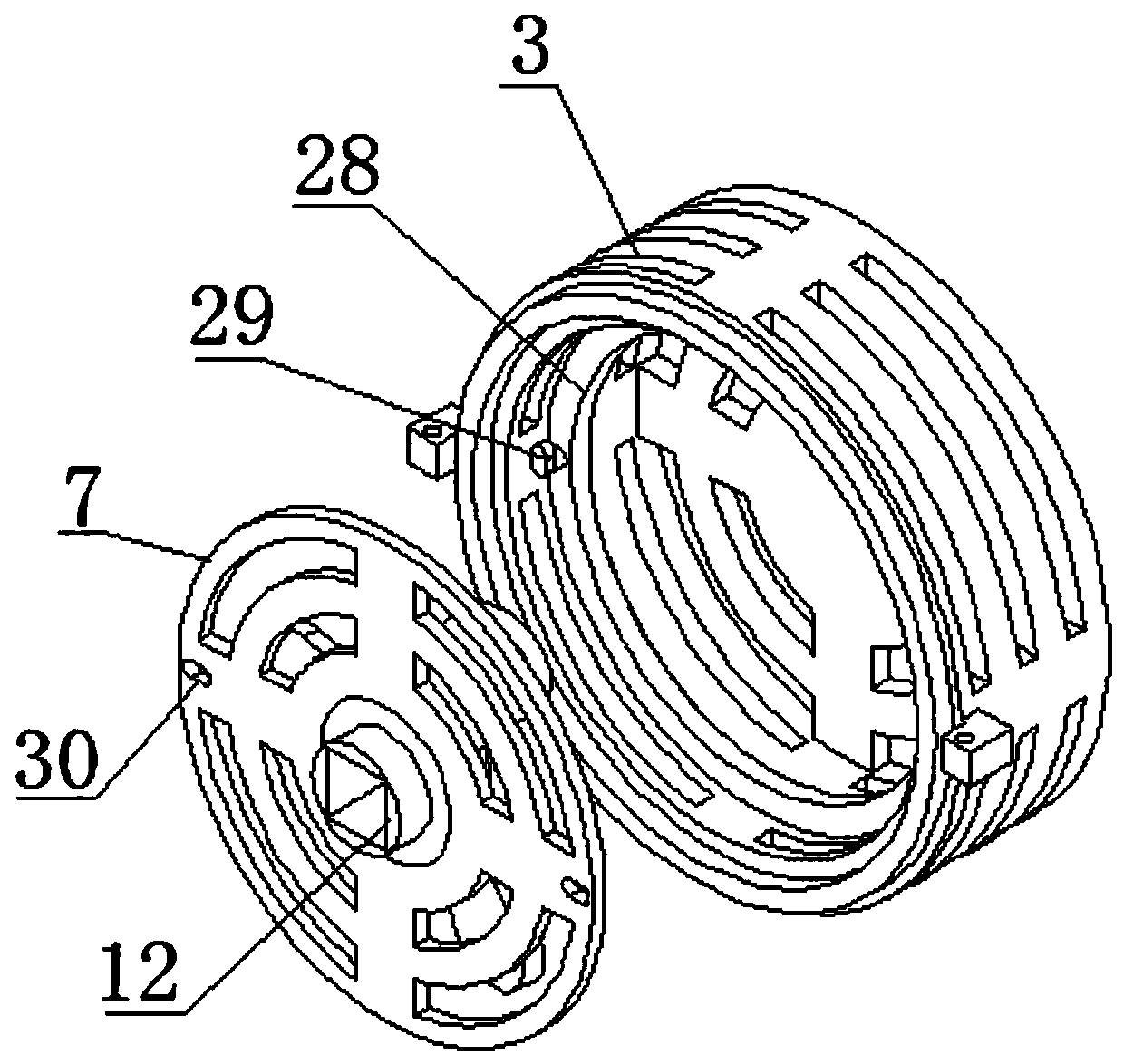
[0029] The embodiment of the present invention discloses the waste heat recovery of the distributed computing power center for cooling and heating units, such as Figure 1-7 As shown, including the unit body 1, the unit body 1 is provided with two protective covers 3 and two fans 4, and the two fans 4 are provided with fan shafts 5, and the protective cover 3 is provided with a mounting plate 7, and the mounting plate 7 A mounting hole 8 is opened on the top, and a bearing 9 is fixedly installed in the mounting hole 8, and a rotating column 10 is fixedly installed in the bearing 9, and a plurality of fan blades 11 located in the protective cover 3 are fixedly installed on the rotating column 10. The bottom side is provided with a connection groove 12, and a connection block 6 is movably installed in the connection groove 12. The bottom side of the connection block 6 is fixedly installed on the top of the fan shaft 5, and two positioning rings 14 are fixedly installed on the uni...


PUM


Abstract

The invention discloses a distributed hashrate center waste heat recovery cooling and heating unit, and relates to the field of cooling and heating units. The distributed hashrate center waste heat recovery cooling and heating unit comprises a unit body, and the unit body is provided with two protective covers and two fans; the two fans are both provided with fan shafts; and each protective coveris internally provided with an installation plate, the installation plate is provided with an installation hole, a bearing is fixedly installed in the installation hole, a rotary column is fixedly installed in the bearing, a plurality of fan blades located in the protective cover are fixedly installed on the rotary column, the bottom side of the rotary column is provided with a connection groove,and the connection groove is internally and movably provided with a connection block. According to the distributed hashrate center waste heat recovery cooling and heating unit, by taking down the protective covers, the installation plates are conveniently taken down, accordingly, the rotary columns can drive the multiple fan blades to be separated from the fan shafts, the fans are exposed, thus, the protective covers are convenient to clean and replace, and meanwhile, the fan blades and the fans are convenient to clean and maintain; and by arranging a plurality of damping springs, vibration can be effectively counteracted, and accordingly, the unit body is effectively protected.

Description

technical field [0001] The invention relates to the technical field of cooling and heating units, in particular to a cooling and heating unit for recovery of waste heat in a distributed computing power center. Background technique [0002] Distributed computing is a computing method, which is relative to centralized computing. Distributed computing decomposes the application into many small parts and assigns them to multiple computers for processing. Multiple computers form a distributed computing power center. Because The particularity of electronic equipment often requires the addition of heating and cooling units to ensure the computing power center. [0003] The existing waste heat recovery cooling and heating units have the following shortcomings. First, the unit is placed outdoors for a long time, and the protective cover is easily affected by extreme weather, such as heavy snow or hail, which will cause damage to the protective cover. However, the existing protective ...

Claims


Application Information

Patent Timeline
Patent Type & Authority Applications(China)
IPC IPC(8): F04D25/08F04D25/16F04D27/00F04D29/64F04D29/66F04D29/70F04D29/58
CPCF04D25/08F04D25/166F04D27/006F04D29/58F04D29/644F04D29/668F04D29/703
Inventor 吴小龙
Owner 江西锋铄新能源科技有限公司
Learn More