
Heat conduction efficiency detection equipment for heat pipe

A testing equipment and heat pipe technology, applied in the field of heat pipe thermal conductivity testing equipment, can solve problems such as difficult and accurate control of the effective length of the heating end and the cooling end, failure to reduce testing costs, inconsistent heat pipe testing standards, etc., and improve testing convenience. , The effect of overcoming inefficient work defects and improving operational convenience

Pending Publication Date: 2020-08-28
TENON HEAT TRANSFER TECH ZHONGSHANCO LTD
View PDF0 Cites 2 Cited by
  • Summary
  • Abstract
  • Description
  • Claims
  • Application Information

AI Technical Summary

Problems solved by technology

In the prior art, all the heat pipes are manually inspected one by one, and the quality of the heat pipes can be ensured only after the heat pipes produced by manpower are screened. The effective length of the end is not easy to accurately control, and the detection standards for heat pipes produced in batches are inconsistent; and the current heat pipe heat conduction detection instruments or equipment are expensive, the operation process is too complicated, and the detection takes a long time, etc., and cannot be used for mass production. All heat pipes are inspected, which fails to achieve the purpose of reducing inspection costs

Method used


Image

  • Heat conduction efficiency detection equipment for heat pipe
  • Heat conduction efficiency detection equipment for heat pipe
  • Heat conduction efficiency detection equipment for heat pipe

Examples


Embodiment Construction

[0044] The technical solutions and beneficial effects of the present invention will be clearer and more definite by further describing the specific implementation manners of the present invention in conjunction with the accompanying drawings of the specification below.

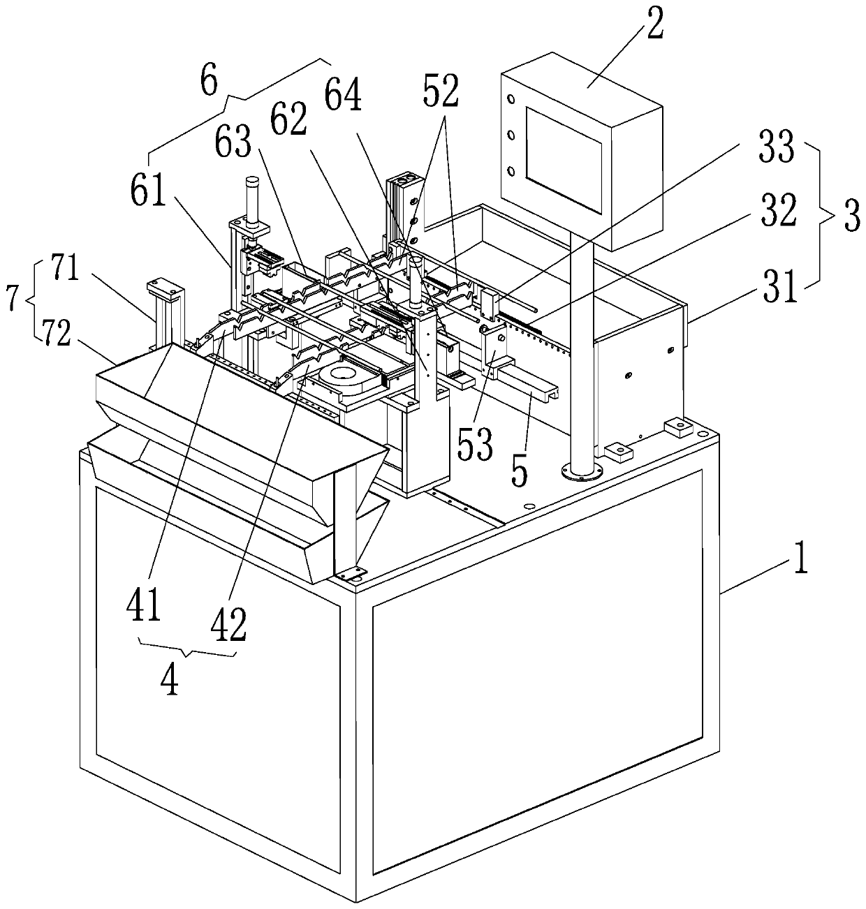
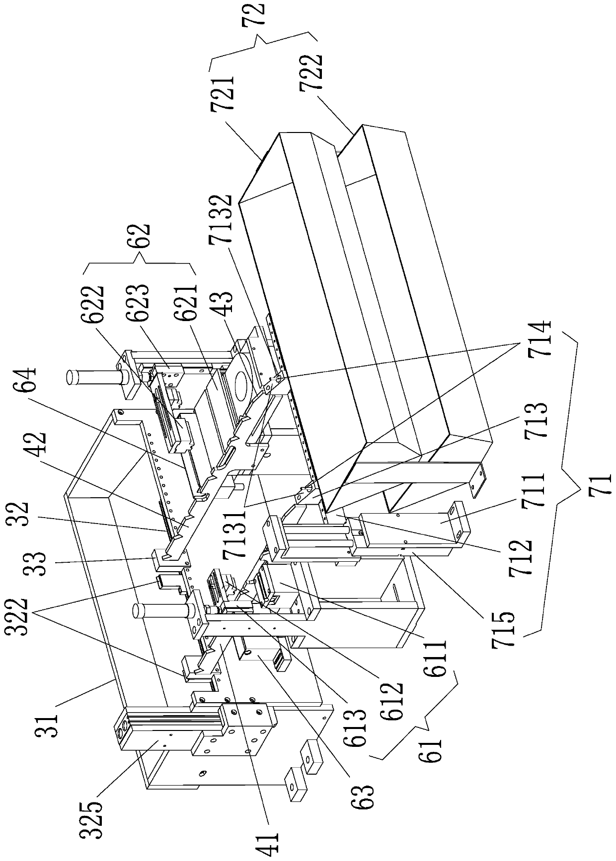
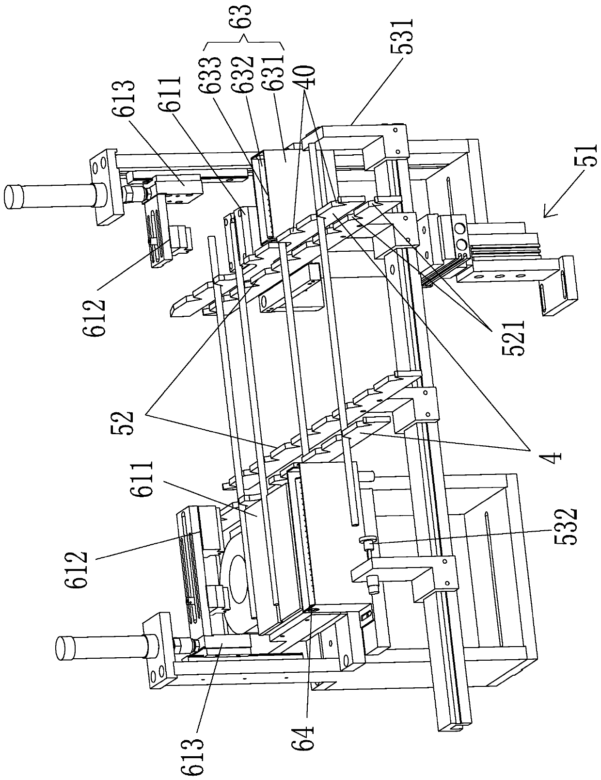
[0045] see Figure 1-8 The shown embodiment discloses a heat pipe heat conduction performance detection device, the heat pipe heat conduction performance detection device, which is installed on the rack 1 and executes the instructions of the controller 2: a feeding mechanism 3 for outputting heat pipes, with The feeding mechanism 4 for receiving and discharging heat pipes is used to accept the heat pipes output by the feeding mechanism and transport the heat pipes to the feeding mechanism 4 for moving. The material transfer mechanism 5 is used to heat the heating end and the cooling end of the heat pipes respectively The detection mechanism 6 for temperature measurement and heat dissipation detection is used t...


PUM


Abstract

The invention discloses heat conduction efficiency detection equipment for a heat pipe. The equipment comprises: a feeding mechanism which is used for outputting heat pipes, a material fixing mechanism which is used for bearing and releasing the heat pipes, a material moving mechanism which is used for bearing the heat pipes output by the feeding mechanism and conveying the heat pipes to the material fixing mechanism to move, a detection mechanism which is used for conducting heating temperature measurement detection and heat dissipation temperature measurement detection on the heating ends and the heat dissipation ends of the heat pipes respectively, and a discharging mechanism which is used for receiving instructions of the controller and outputting the detected heat pipes in a classified mode, which are installed on a rack and execute the instructions of a controller. According to the invention, all mass-produced heat pipes can be rapidly detected, and the operation process is simple, the effective lengths of the heating end and the heat dissipation end can be accurately controlled during mass production detection, the consistency of detection standards of various batches of mass-produced heat pipes is ensured, the measured heat pipes are ensured to have good uniformity, reproducibility and reliability, the labor cost is effectively saved, the purpose of reducing the detection cost is achieved, and the beneficial effects of accurate detection and rapid feeding and discharging are achieved.

Description

technical field [0001] The invention relates to the technical field of heat pipe detection, in particular to a heat pipe heat conduction efficiency detection device. Background technique [0002] Generally, the heat pipe is composed of a tube shell, a liquid-absorbing core and an end cap. After the tube is pumped into negative pressure, it is filled with an appropriate amount of working liquid, so that the porous capillary structure layer of the liquid-absorbing core close to the inner wall of the tube is filled with liquid and then sealed. Thus, one end of the heat pipe is the evaporation section (heating end), the other end is the condensation section (radiation end), and the space in the center is empty, and an insulating section can be arranged between the two sections according to application requirements. When the heating end of the heat pipe absorbs heat, the liquid-phase operating fluid contained in the tube wall evaporates, thereby increasing the vapor pressure to f...

Claims


Application Information

Patent Timeline
IPC IPC(8): G01N25/20B07C5/36B07C5/38B07C5/02
CPCB07C5/02B07C5/362B07C5/38G01N25/20
Inventor 林琼榕张玉峰陈海强
Owner TENON HEAT TRANSFER TECH ZHONGSHANCO LTD
Learn More